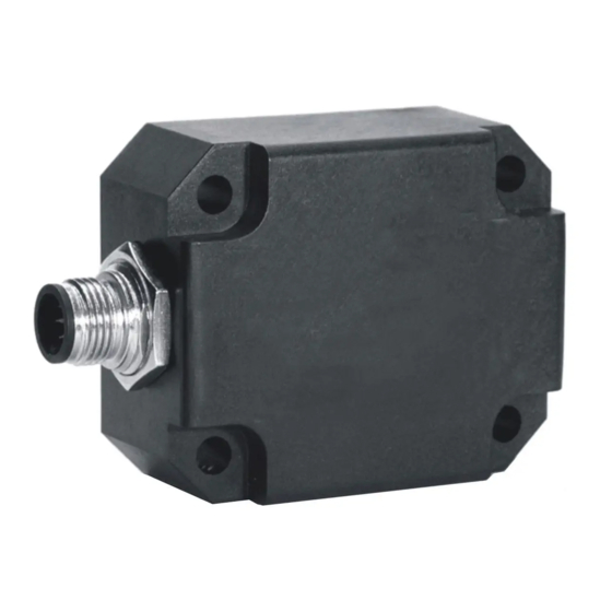
DIS Sensors CAN Manuale d'uso - Pagina 2
Sfoglia online o scarica il pdf Manuale d'uso per Accessories DIS Sensors CAN. DIS Sensors CAN 18. Inclination safety sensor

CAN User Manual
Inclination Safety Sensor
(Type D) V2.0
1
Introduction................................................................................................................................................ 3
2
Quick Reference Guide .............................................................................................................................. 3
3
Safety, Installation, use & maintenance ..................................................................................................... 4
4
Certification ............................................................................................................................................... 5
5
Inclination sensor explained ...................................................................................................................... 5
6
Safety function ........................................................................................................................................... 5
7
Hardware setup .......................................................................................................................................... 5
8
Signal processing ....................................................................................................................................... 6
8.1
Sample rate: .................................................................................................................................... 6
8.2
Averaging: ...................................................................................................................................... 6
8.3
Output filter: ................................................................................................................................... 6
8.4
Peak Suppression Filter: ................................................................................................................. 7
8.5
Pre-set/zero adjustment: ................................................................................................................. 7
8.6
Accelerator element tolerance ........................................................................................................ 8
8.7
Output invalid ................................................................................................................................. 8
8.8
Writing objects ............................................................................................................................... 8
8.9
Changing SRDO1 settings .............................................................................................................. 8
9
Internal diagnostic tests ............................................................................................................................. 9
CAN Predefined Connection Object ID's ................................................................................................ 10
10
11
CAN Object Dictionary Entries (Communication Profile section) .......................................................... 11
12
CAN Object Dictionary Entries 360v device (Application Specific Profile section) .............................. 13
13
CAN Object Dictionary Entries ±30h and ±90h devices (Application Specific Profile section) ............ 15
14
EDS files .................................................................................................................................................. 17
15
Document revision control ....................................................................................................................... 17
Appendixes1 Schematic overview inclination measurement ................................................................... 18
Figure 1: Layout CAN bus connector .......................................................................................................................... 5
Figure 2: Schematic overview inclination measurement. ........................................................................................ 18
Table 1 Object fields for zero value (pre-set) CRC calculation ................................................................................... 7
Table 2: Emergency code ........................................................................................................................................... 9
Table 3: COB id's ...................................................................................................................................................... 10
Table 4: Communication profile section .................................................................................................................. 11
Table 5 Application specific profile section for 360 degree device .......................................................................... 13
Table 6: Application specific profile section for ±30h and ±90h devices ................................................................. 15
Table of Contents
List of Figures
List of Tables
Page 2 of 18
