- ページ 2
コントローラー COMECO RT1900-RのPDF 操作マニュアルをオンラインで閲覧またはダウンロードできます。COMECO RT1900-R 4 ページ。 Universal pid controller
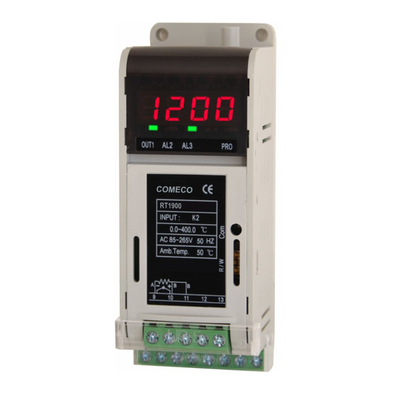
Table of Contents
Overview
3
Mounting
3
Wiring
4
Indication and Controls
5
Program Levels
6
Level 1 (User Level)
7
Program Level 2
8
Program Level 3 (I)
9
Program Level 3 (II)
10
Program Level 3 (III)
11
Output Control
12
Alarm modes
13
Communication
14
Error Messaging
14
EMI Issues
15
Declaration of Conformity
15
Waste Disposal
15
Specifications
16
Warranty and Support
16
Wiring
protectors from terminal blocks prior wiring!
Install the protectors again when finish!
Input signal wiring
♦
♦
♦
♦
Serial interface wiring
Connect RT1900-R to RS485 interface
line via terminals 12(Dx-) and 13(Dx+).
Output wiring
♦
♦
Power supply wiring
Connect the power supply voltage
to terminals 1(L) and 2(N).
Gently remove transparent plastic
Connect Pt100 sensors to terminals
9, 10 and 11, or T/C sensors to
terminals 9(-) and 10(+).
Connect linear mV/V signal to
terminals 9(-) and 10(+).
Connect linear mA signal to terminals
9(-) and 10(+) paralleled with
enclosed 2.5 Ω external resistor.
Transmitters must be powered from
external sources!
Connect relay, SSR and MOS gate
outputs to the respective terminals
3...8 as shown on the left figure.
Connect analog outputs and external
SSRs to the respective terminals 3...8
as shown on the left.
Electro-Magnetic Interference (EMI) Issues
2
Important note:
RT1900 may content a
RC noise suppression
circuit is connected in
parallel with relay
contacts.
Full AC voltage isolation
is NOT provided when
relay contacts are open.
Small AC current
(≈ 1.5 mA at 230 VAC)
still flows through
the RC circuit!
Declaration of Conformity
Waste Disposal
Do not
dispose of
electronic
devices
together with
household
waste!
Alarm modes
4
Table 2 (Alarm modes)
Alarm function
Alarm action is suppressed at start-up
until PV enters non-alarm range!
Alarm action is suppressed at start-up
until PV enters non-alarm range!
Alarm action is suppressed at start-up
until PV enters non-alarm range!
Alarm action is suppressed at start-up
until PV enters non-alarm range!
Alarm action is suppressed at start-up
until PV enters non-alarm range!
♦
All signal wires must be shielded. They must
not be packaged together with power cables!
♦
Never lay the signal wires close to inductive or
capacitive noise sources, such as relays,
contactors, motors, etc.!
♦
All shields have to be grounded ONLY at one
end, as closer as possible to device terminals!
♦
Avoid sharing supply lines with powerful
consumers, especially with inductive loads,
switched on and off.
♦
To stop unwelcome interference signals
entering through the power supply lines,
use shielded 1:1 isolation transformer!
♦
Shunt all switched (not only those switched
by the indicator) inductive consumers with
special suppression networks: RC group and
varistor - for AC loads, or diode - for DC loads.
♦
If the indicator operates in a very powerful
EMI area, it has to be mounted inside
a grounded metal shielding box!
We hereby declare that this device has been
manufactured in compliance with standards
EN 61000, EN 61010 and EN 61326,
and meets the requirements of Directives
2004/108/EC, 2006/95/EC and 2011/65/EC.
Vladimir Sakaliyski, CEO
COMECO Inc.
If disposed of within European Union,
this product should be treated
and recycled in accordance with the laws
of your jurisdiction implementing
the WEEE Directive 2002/96
on the Waste Electrical and Electronic Equipment.
Alarm modes with their type and codes
(referenced to ALd1, ALd2, ALd3):
Code
Description
00/10
No alarm
Relative HIGH alarm
11
Deviation from SV high alarm
same as code 11,
01
but with suppression
Relative LOW alarm
12
Deviation from SV low alarm
same as code 12,
02
but with suppression
Window alarm
13
Deviation from SV high/low
alarm
same as code 13,
03
but with suppression
Band alarm
04/14
Deviation from SV
Process HIGH alarm
15
Exceeding absolute value
same as code 15,
05
but with suppression
Process LOW alarm
16
Falling below absolute value
same as code 16,
06
but with suppression
System alarm ON
08
Activating at errors
UUU1, nnn1 or CJCE
System alarm OFF
18
Not activating at above errors
15
13