- ページ 4
コントローラー COMECO RT1900-RのPDF 操作マニュアルをオンラインで閲覧またはダウンロードできます。COMECO RT1900-R 4 ページ。 Universal pid controller
Program Levels
Program Level 2 (PID Level)
P1
0
↓ SET
i1
240
↓ SET
d1
60
↓ SET
db1
0
↓ SET
AtVL
0
↓ SET
CYt1
10
↓ SET
HYS1
1
↓ SET
P2
0
↓ SET
i2
240
↓ SET
d2
60
↓ SET
CYt2
10
↓ SET
HYS2
1
↓ SET
GAP1
0
↓ SET
GAP2
0
↓ SET
LC"
0000
↓ SET
Return to P1
Basic state
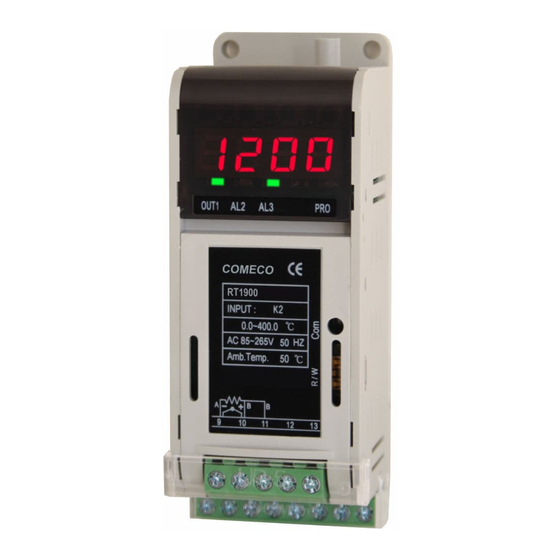
After power-on RT1900-R
performs a system check
and enters its Basic state
showing PV with a
resolution, according to
the dP parameter.
SV adjustment
Form Basic state press
key and adjust the SV.
Press SET key to return.
If press no key, RT1900-
R will return to Basic state
automatically within 60 s.
LEVEL 1 (User Level)
Form Basic state press
SET key to enter and the
same key to return.
If press no key, RT1900-
R will return to Basic state
automatically within 60 s.
LEVEL 2 (PID Level)
Form Basic state press
and hold SET key for ~5 s
to enter.
Return the same way.
If press no key, RT1900-
R will return to Basic state
automatically within 60 s.
LEVEL 3 (Input Level)
Form Basic state press
and hold SET+
~5 s to enter. Return by
using the same keys.
If press no key, RT1900-
R will return to Basic state
automatically within 60 s.
Programming procedure
♦
From Level 1 (User level) press
SET key for ~5s to enter Level 2.
♦
Set PID proportional band for OUT1
(0.0 to 200.0 %, 0.0 converts PID to ON/OFF).
♦
Set PID integral time for OUT1
(0 to 3600 s, 0 converts PID to PD).
♦
Set PID derivative time for OUT1
(0 to 900 s, 0 converts PID to PI).
♦
Set dead-band time for OUT1
(do not care - let stay 0).
♦
Set auto-tuning offset value (0 to USPL).
♦
Set circle time for OUT1 (0 to 150 s)
Recommended: 10 for relay and 0 - for mA.
♦
Set hysteresis for OUT1 if ON/OFF control is
set with P1=0 (0 to 1000, with PV units).
♦
Set PID proportional band for OUT2
(0.0 to 200.0 %, 0.0 converts PID to ON/OFF).
♦
Set PID integral time for OUT2
(0 to 3600 s, 0 converts PID to PD).
♦
Set PID derivative time for OUT2
(0 to 900 s, 0 converts PID to PI).
♦
Set circle time for OUT2 (0 to 150 s)
Recommended: 10 for relay and 0 - for mA.
♦
Set hysteresis for OUT2 if ON/OFF control is
set with P2=0 (0 to 1000, with PV units).
♦
Set dead-band gap for OUT1 (heating):
set-point= SV-GAP1 (if in doubt, set to 0)
♦
Set dead-band gap for OUT2 (cooling):
set-point= SV+GAP2 (if in doubt, set to 0)
♦
Parameter change lock:
0000 - ALL parameters can be changed
0100 - change Level 1(2) parameters only
0110 - change Level 1 parameters only
0001 - change SV and LC" only
0101 - change LC" only
Program Level 3 (Input Level) - III
6
↓
ALd2
↓ SET
ALt2
↓ SET
ALd3
↓ SET
ALt3
↓ SET
HYSA
↓ SET
CL01
↓ SET
CH01
↓ SET
PSL
↓ SET
bitS
↓ SET
1 p0
↓ SET
bAUd
↓ SET
PV0S
↓ SET
Up1t
↓ SET
PVFt
keys for
↓ SET
0Ud
↓ SET
Hz
↓ SET
Return to 1pP1
Program Level 3 (Input Level) - I
8
(1)
T/C type
Code
K1
K2
K3
'K'
K4
K5
(2)
K6
J1
J2
J3
'J'
J4
J5
J6
R1
'R'
R2
SS1
'S'
S2
'B'
B1
E1
'E'
E2
N1
'N'
N2
T1
'T'
T2
T3
W1
'W'
W2
PL1
'PLII'
PL2
U1
'U'
U2
U3
L1
'L'
L2
♦
Select AL2 alarm mode
0
(2-digit code from Table 2, 'Alarm modes').
♦
Set AL2 alarm ON delay time [mm.ss]
9(59
(99.59: continued action, 00.00: flicker alarm).
♦
0
Select AL3 alarm mode
(2-digit code from Table 2, 'Alarm modes').
♦
9(59
Set AL3 alarm ON delay time [mm.ss]
(99.59: continued action, 00.00: flicker alarm).
♦
0
Set hysteresis of all alarms
(0 to 1000, with PV resolution and units).
♦
230
For analog control output, set LOW-point
calibration value (0 to 9999).
♦
3600
For analog control output, set HIGH-point
calibration value (0 to 9999).
♦
rtU
For RS485 interface, select communication
protocol (MODBUS-RTU or MODBUS-ASCII).
♦
o_81
For RS485 interface, select bit format
(0_81: 1 stop/no, 0_82: 2 stop/no),
(E_81: 1 stop/even, E_82: 2 stop/even).
♦
1
For RS485 interface, select unit ID (0 to 255).
♦
For RS485 interface, select baud-rate
384
(2400, 4800, 9600,
♦
PV correction [offset] (-1000 to 1000).
)0
♦
PV/SV engineering units
C
(°C, °F or A -for analog linear input).
♦
200
PV filter (smaller values - for faster
response, bigger values - for better filtration).
♦
HEAt
Control action mode [direction of action]
(Heat or Cool).
♦
50Hz
Mains power supply frequency (50 or 60 Hz)
Select the proper frequency
for your country!
Table 1 (Input types and codes)
Range [°C]
RTD type
0.0 ÷ 200.0
01
JP1
0.0 ÷ 400.0
02
JP2
0 ÷ 600
03
JP3
Pt100
0 ÷ 800
1.381
04
JP4
0 ÷ 1000
05
JP5
0 ÷ 1200
06
JP6
0.0 ÷ 200.0
07
DP1
0.0 ÷ 400.0
08
DP2
0 ÷ 600
09
DP3
Pt100
0 ÷ 800
1.385
10
DP4
0 ÷ 1000
11
DP5
0 ÷ 1200
12
DP6
0 ÷ 1600
13
Analog Linear Code
0 ÷ 1769
14
0 ÷ 1600
15
AN1
0 ÷ 1769
16
0 ÷ 1820
17
0 ÷ 800
18
AN2
0 ÷ 900
19
AN3
0 ÷ 1200
20
0 ÷ 1300
21
22 -199.0 ÷ 400.0
23 -199.0 ÷ 200.0
AN4
0.0 ÷ 350.0
24
0 ÷ 2000
25
0 ÷ 2320
26
0 ÷ 1300
27
0 ÷ 1390
28
AN5
-199.0 ÷ 600.0
29
-199.0 ÷ 200.0
30
0.0 ÷ 400.0
31
(1) Changing from T/C to Pt100 and vice-versa
0 ÷ 400
32
requires hardware adjustment
0 ÷ 800
33
(2) Default input configuration setting
(3) Display ranges for all linear choices can be:
-1999÷9999 with 0, 0.0 0.00 or 0.000 DP
(4) Requires 2R5 external resistor in parallel
11
19200
or
38400
bps).
9
(1)
Code
Range [°C]
-199.0 ÷ 600.0
41
-199.0 ÷ 400.0
42
-199.0 ÷ 200.0
43
0 ÷ 200
44
0 ÷ 400
45
0 ÷ 600
46
-199.0 ÷ 600.0
47
-199.0 ÷ 400.0
48
-199.0 ÷ 200.0
49
0 ÷ 200
50
0 ÷ 400
51
0 ÷ 600
52
(3)
Range
-10 ÷ 10 mV
61
-2 ÷ 2 V
62
-5 ÷ 5 V
63
-10 ÷ 10 V
64
0 ÷ 10 mV
71
0 ÷ 20 mV
76
0 ÷ 50 mV
81
(4)
0 ÷ 20 mA
82
0 ÷ 1 V
83
0 ÷ 5 V
84
0 ÷ 10 V
85
0 ÷ 5 kΩ
86
0 ÷ 2 V
87
10 ÷ 50 mV
91
(4)
4 ÷ 20 mA
92
1 ÷ 5 V
93
2 ÷ 10 V
94