- ページ 3
コントローラー COMECO RT1900-RのPDF 操作マニュアルをオンラインで閲覧またはダウンロードできます。COMECO RT1900-R 4 ページ。 Universal pid controller
Output Control
Program Level 3 (Input Level) - II
Input hardware selection
♦
♦
♦
♦
Programming procedure
♦
♦
♦
1pP1
"2
↓ SET
♦
ApL1
0
↓ SET
♦
ApH1
5000
↓ SET
♦
dP
0000
↓ SET
♦
lS L
)0
↓ SET
♦
aS L
40)0
↓ SET
♦
ALd1
11
↓ SET
♦
ALt1
9(59
↓ SET
ON/OFF control
The static
characteristic
of a relay controlled
by an ON/OFF
algorithm is shown on
the left.
PID control
The relationship
between PID input and
output when both
integration and
differentiation are
switched off is
illustrated on the left.
PID-control internal
structure is shown on
the left figure.
Alarm output control
The static
characteristic
of an alarm relay is the
same as for ON/OFF
control.
Alarm time
characteristics
(referenced to ALt1,
ALt2, ALt3) are
illustrated on the left.
To be completed BEFORE installation!
Insert 2 flat-tip screwdrivers in the slots
located on both sides of the front protection
cover (1).
Gently press the side plastic walls outwards
in order to remove 2 fixing pins (2) from their
slots (3) and then open the cover (1) rotating
it up.
Find the input jumper located on the right
side of the terminal.
Place the jumper bridge in UP position for
T/C or in DOWN position for Pt100 input.
First go to Level 2 and set LC" to 0000.
From Level 1 (User level) press
SET+
keys for ~5s to enter Level 3.
Set input type by selecting it from Table 1.
For analog linear input, set display value for
LOW input range (-1999 to 9999).
For analog linear input, set display value for
HIGH input range (-1999 to 9999).
For analog linear input, set decimal point
position (0000, 000.0, 00.00 or 0.000)
Set LOW set-point limit
(within PV range, resolution and units).
Set HIGH set-point limit
(within PV range, resolution and units).
Select AL1 alarm mode
(2-digit code from Table 2, 'Alarm modes').
Set AL1 alarm ON delay time [mm.ss]
(99.59: continued action, 00.00: flicker alarm).
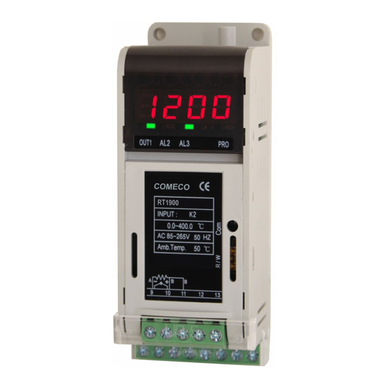
Indication and Controls
12
Level 1 (User Level)
10
main
alternative
indication
indication
Power ON
↓
8888
↓
1pP1
"6
↓
1200
0
↓
25
25
↓
0000
adjust SV
↓ SET
25
25
↓ SET
At
no
↓ SET
AL1
0
↓ SET
AL2
0
↓ SET
AL3
0
↓ SET
25
Brawn-transparent plastic cover
to protect display and keyboard
(pull the upper edge to open)
Keyboard of 4 push switches
4-digit 8mm red LED display
Status LED indicators
- Lamp 1: OUT1 or AL1
- Lamp 2: OUT2 or AL2
- Lamp 3: AL3
- Lamp 4: running program
(for pattern control only)
Front protection plastic cover.
Should be opened ONLY for
hardware input selection
(see 'Program Level 3')
Communication status LED
USB terminal for parameter
save and restore
Upper terminal block (5-pin)
for input and interface wiring
Lower terminal block (8-pin)
for output and power wiring
DIN-rail fixing slide
Both display and front
protection cover must
be well closed during
operation!
Working with covers
open may lead to
human injury caused
by electric current!
Power ON sequence
After turning power on, RT1900-R automatically
makes some system tests:
♦
Checks indication integrity
(display and all LEDs)
♦
Shows input type.
♦
Shows input HIGH and LOW
range limits (Table 1).
♦
Automatically returns to basic state
showing PV.
Set-point (SV) adjustment
♦
Press
to enter SV adjustment mode.
♦
Adjust the set-point from LSPL to USPL
(with PV resolution and units).
Select a blinking digit with
, adjust
digit value with
and
,confirm with SET.
♦
Return to basic state showing PV.
Other user-level adjustments
♦
Turn ON auto-tuning by selecting YES
(returns to no after finishing).
♦
Set AL1 set value
(if used, with PV resolution and units).
♦
Set AL2 set value
(if used, with PV resolution and units).
♦
Set AL3 set value
(if used, with PV resolution and units).
♦
Return to basic state showing PV.
5
7