- ページ 21

産業機器 Siemens SINAMICS G120PのPDF 取扱説明書をオンラインで閲覧またはダウンロードできます。Siemens SINAMICS G120P 28 ページ。 Line reactors for power modules pm330
Siemens SINAMICS G120P にも: 取扱説明書 (26 ページ), 取扱説明書 (34 ページ), 取扱説明書 (24 ページ), 取扱説明書 (22 ページ), 取扱説明書 (26 ページ), 取扱説明書 (22 ページ), 取扱説明書 (22 ページ), マニュアル (18 ページ), 取扱説明書 (18 ページ)
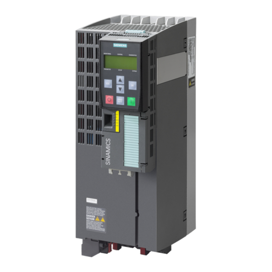
Siemens SINAMICS G120P 取扱説明書
Connection
When connecting the du/dt reactor and Voltage Peak Limiter, you must take into account the
following conditions to ensure that it functions correctly:
● Control cables must be routed separately from power cables. Power cables are the motor
● It is recommended to use shielded motor cables. If a shielded motor cable is used, its
● The ground wire for the motor must be fed directly back to the Power Module.
Connection overview
Figure 4-3
Cable cross-sections
Table 4- 1
Cable cross-sections for connections between the du/dt filter plus Voltage Peak Limiter and Power Module
du/dt filter plus Voltage Peak
Limiter
6SL3000-2DE35-0AA0
6SL3000-2DE38-4AA0
dV/dt filter plus Voltage Peak Limiter
Operating Instructions, 04/2014, A5E32847105B AB
cable or the connecting cables from the DC link of the Power Module (terminals
DCP/DCN) to the Voltage Peak Limiter. In particular, you must ensure that control cables
and power cables are not routed in parallel in a joint cable raceway, even if all the cables
are shielded.
shield should be connected through a large surface area with the shield connection plate
in the cabinet and at the motor housing.
Connecting a du/dt filter plus Voltage Peak Limiter
Connection to the DC link
(DCPS/DCNS)
Line voltage 380 V – 480 V 3 AC
[mm²]
70
2 x 50
Electrical installation
Connection between du/dt reactor and
voltage peak limiter
(1U2, 1V2, 1W2) [mm²]
16
50
21