- ページ 6

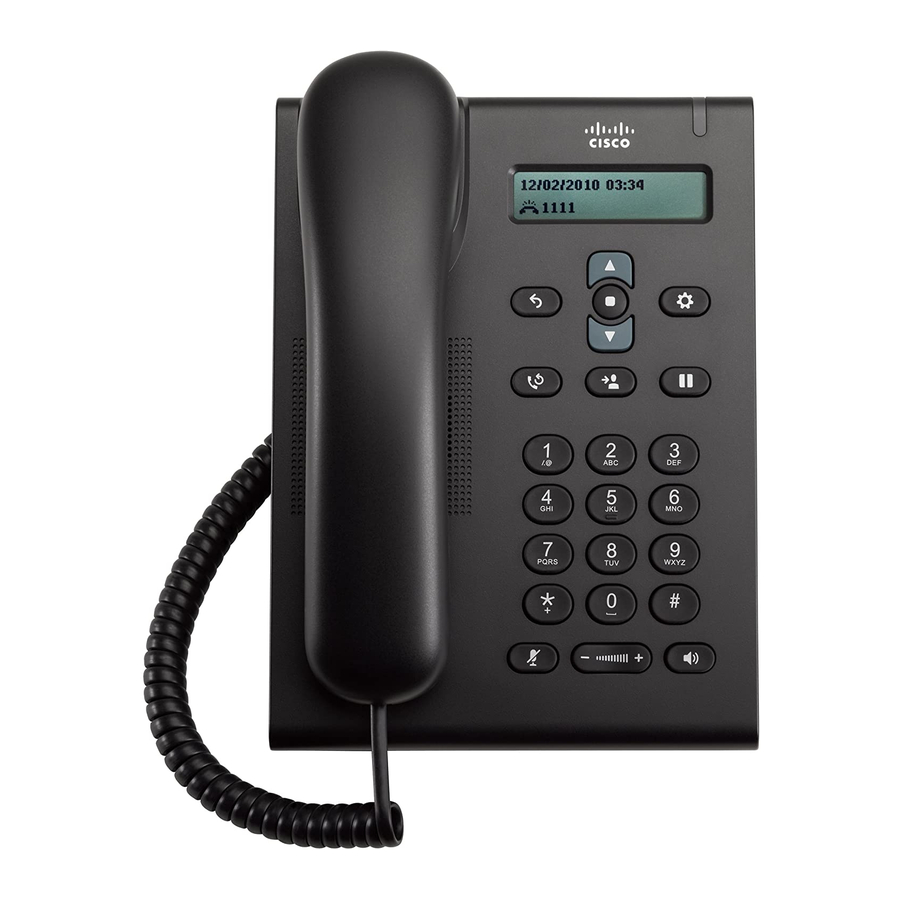
IP電話 Cisco 3905のPDF ユーザーマニュアルをオンラインで閲覧またはダウンロードできます。Cisco 3905 16 ページ。 Cisco systems telephone user manual
Cisco 3905 にも: ユーザーマニュアル (14 ページ), ユーザーマニュアル (40 ページ), ユーザーマニュアル (2 ページ), ユーザーマニュアル (3 ページ), 特徴 (6 ページ), ユーザーマニュアル (40 ページ), 特徴 (11 ページ), ユーザーマニュアル (36 ページ), クイック・リファレンス・マニュアル (2 ページ), マニュアルの使用 (16 ページ), ユーザーマニュアル (2 ページ), (ポルトガル語)クイック・スタート・マニュアル (1 ページ)

Cisco 3905 ユーザーマニュアル
6 • UK

2.3 EFC21 standard installation

Description
The diagram shows how a separate solenoid valve (SMG) must be connected to the EFC21. The
solenoid valve is part of the separate fail-safe system and will cut off the gas supply in the case of
insufficient system chimney draught (controlled by the fan pressure switch).
• Connect the earths of the mains supply, chimney fan and solenoidvalve
together (SMG).
• Connect the chimney fan and pressure switch to terminals 1–5.
• Connect the SMG to terminals 6–7.
• Connect the optional Air inlet monitoring to terminals 10–11. If this monitoring is not manda-
tory, then a jumper must be fitted across terminals 10–11.
• Connect mains supply to terminals marked "Supply".
Wiring diagram
Fig. 6
Unit
Fig. 7
Chimney fan with pressure switch (PDS)
Isolation switch
EFC21
SMG (solenoid valve)
3001736-EFC21-EFC25-UK
Mains
Gas