- ページ 5

IP電話 Cisco 3905のPDF ユーザーマニュアルをオンラインで閲覧またはダウンロードできます。Cisco 3905 16 ページ。 Cisco systems telephone user manual
Cisco 3905 にも: ユーザーマニュアル (14 ページ), ユーザーマニュアル (40 ページ), ユーザーマニュアル (2 ページ), ユーザーマニュアル (3 ページ), 特徴 (6 ページ), ユーザーマニュアル (40 ページ), 特徴 (11 ページ), ユーザーマニュアル (36 ページ), クイック・リファレンス・マニュアル (2 ページ), マニュアルの使用 (16 ページ), ユーザーマニュアル (2 ページ), (ポルトガル語)クイック・スタート・マニュアル (1 ページ)
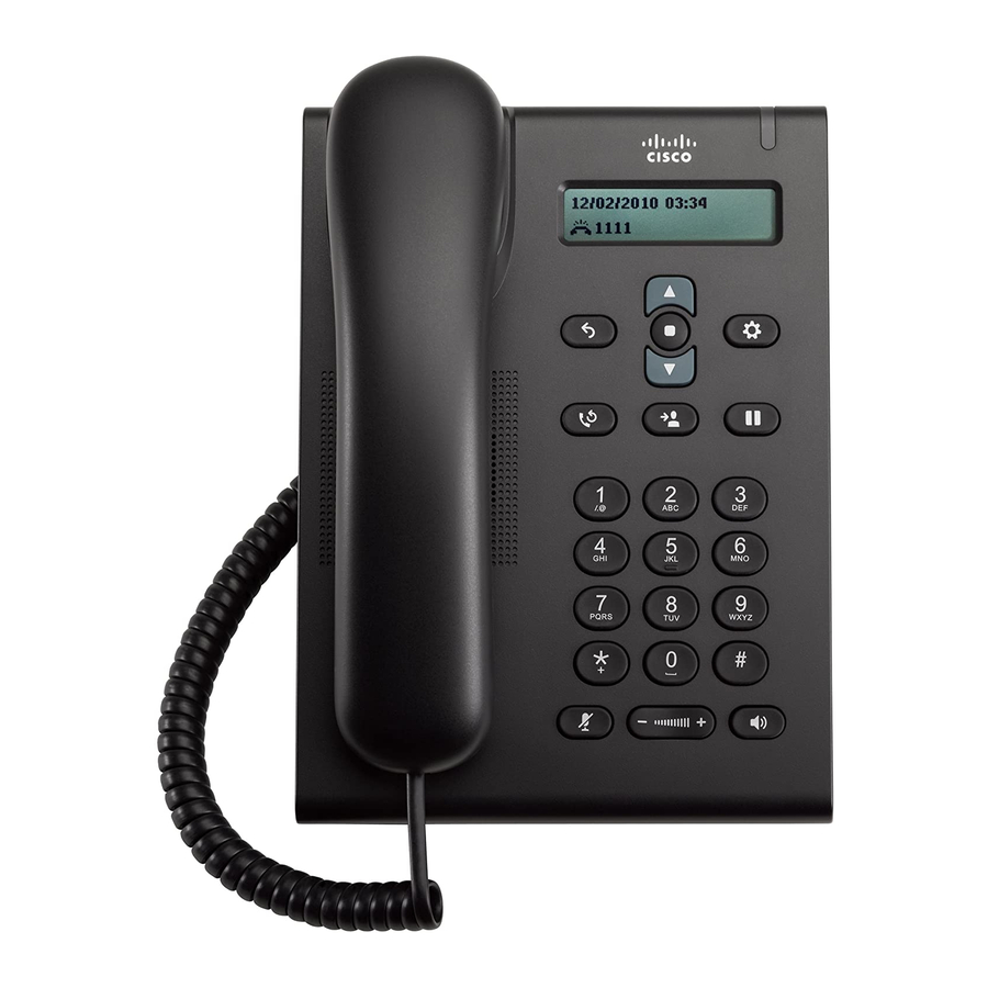
Cisco 3905 ユーザーマニュアル
3001736-EFC21-EFC25-UK

2. Installation

2.1 Fitting the controller

The control panel must be fitted onto a level surface with a minimum distance of 100 mm to any
corner.
The front cover is removed from the frame by twisting a screwdriver in the two holes on the sides
of the cover. The front cover can then be tipped carefully and the frame can be fitted onto the wall.
Fig. 3
NB:
The front cover is fitted with connection cable on the right side which limits how much this side
can be opened.
The controller covers a standard dry lining box (80 x 80 mm).
When fitting an external IR receiver avoid bending the black part of the cable
(EFC25 accessory)(Fig. 4).
Fig. 4

2.2 Electrical wiring

!
• All installations must be carried out by competent personnel in accordance with
national legislation and regulations.
• An isolation switch must be installed between the controller and the chimney fan.
• Refer to the chimney fan instruction when installing the isolation switch.
• The isolation switch must be ordered separately as it is not part of the
standard exodraft delivery.
• Do not connect SMG terminals 6 and 7 to any valve other than an SMG valve supplied
by exodraft.
Fig. 5
• Electrical wiring of the controller must be carried out in accordance with national
legislation and regulations.
• Earth must always be connected.
110
65
UK 5