Cisco 3905 사용자 설명서 - 페이지 5

{카테고리_이름} Cisco 3905에 대한 사용자 설명서을 온라인으로 검색하거나 PDF를 다운로드하세요. Cisco 3905 16 페이지. Cisco systems telephone user manual
Cisco 3905에 대해서도 마찬가지입니다: 사용자 설명서 (14 페이지), 사용자 설명서 (40 페이지), 사용자 설명서 (2 페이지), 사용자 설명서 (3 페이지), 특징 (6 페이지), 사용자 설명서 (40 페이지), 특징 (11 페이지), 사용자 설명서 (36 페이지), 빠른 참조 매뉴얼 (2 페이지), 매뉴얼 사용 (16 페이지), 사용자 설명서 (2 페이지), (포르투갈어) 빠른 시작 설명서 (1 페이지)
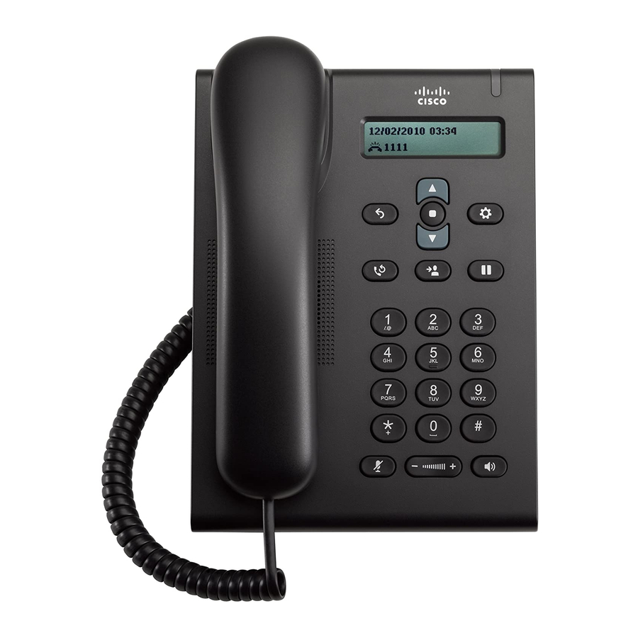
Cisco 3905 사용자 설명서
3001736-EFC21-EFC25-UK

2. Installation

2.1 Fitting the controller

The control panel must be fitted onto a level surface with a minimum distance of 100 mm to any
corner.
The front cover is removed from the frame by twisting a screwdriver in the two holes on the sides
of the cover. The front cover can then be tipped carefully and the frame can be fitted onto the wall.
Fig. 3
NB:
The front cover is fitted with connection cable on the right side which limits how much this side
can be opened.
The controller covers a standard dry lining box (80 x 80 mm).
When fitting an external IR receiver avoid bending the black part of the cable
(EFC25 accessory)(Fig. 4).
Fig. 4

2.2 Electrical wiring

!
• All installations must be carried out by competent personnel in accordance with
national legislation and regulations.
• An isolation switch must be installed between the controller and the chimney fan.
• Refer to the chimney fan instruction when installing the isolation switch.
• The isolation switch must be ordered separately as it is not part of the
standard exodraft delivery.
• Do not connect SMG terminals 6 and 7 to any valve other than an SMG valve supplied
by exodraft.
Fig. 5
• Electrical wiring of the controller must be carried out in accordance with national
legislation and regulations.
• Earth must always be connected.
110
65
UK 5