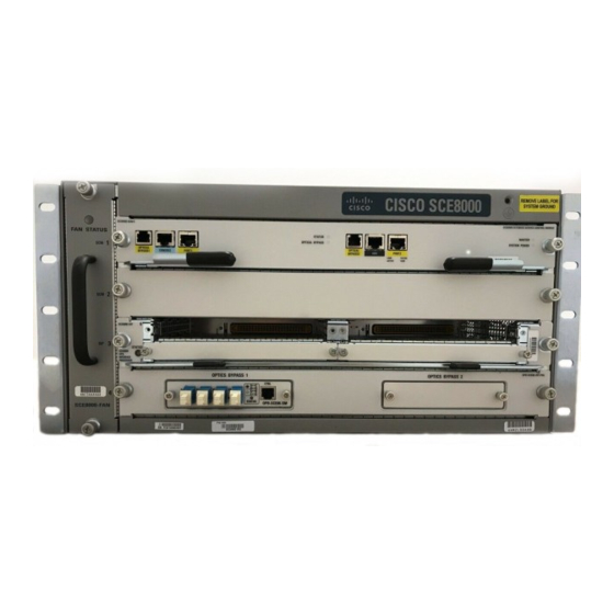
- ページ 4
サーバー Cisco SCE8000 GBEのPDF インストールをオンラインで閲覧またはダウンロードできます。Cisco SCE8000 GBE 21 ページ。 10gbe platform
Cisco SCE8000 GBE にも: クイック・スタート・マニュアル (25 ページ), 設定マニュアル (18 ページ), 取り外しと交換の手順 (36 ページ)

Site Requirements
Table 4-1
Airflow Intake
Right side
Table 4-2
Specification
Temperature
Relative humidity
Heat dissipation
Power Requirements
Warning
Read the installation instructions before connecting the system to the power source.
Follow these requirements when preparing your site for the Cisco SCE8000 installation:
•
•
•
•
Cisco SCE8000 10GBE Installation and Configuration Guide
4-4
Chassis Airflow Requirements
Airflow Exhaust
Left side
Ambient Temperature and Humidity Requirements for the Cisco SCE 8000
The redundant power configuration provides a second, identical power supply to ensure that power
to the chassis continues uninterrupted if one power supply fails or input power on one line fails.
Connect each of the two power supplies to a separate input power source. If you fail to do this, your
system might be susceptible to total power failure because of a fault in the external wiring or a
tripped circuit breaker.
To prevent a loss of input power, be sure that the total maximum load on each circuit supplying the
power supplies is within the current ratings of the wiring and breakers.
In some systems, you might use an uninterruptible power supply (UPS) to protect against power
failures at your site. Avoid UPS types that use ferroresonant technology. These UPS types can
become unstable with systems like the Cisco SCE8000, which can have substantial current draw
fluctuations because of bursty data traffic patterns.
Air Filter Option
Not applicable
Acceptable Range
Nominal: 32°F to 104°F (0°C to 40°C)
Storage: -4°F to 149°F (-20°C to 65°C)
Operating: 10% to 85%
Storage: 5% to 95% (non-condensing)
Single SCE8000-SCM-E module:
•
AC Power: 950 W / 3250 BTUs
–
DC Power: 1000 W / 3450 BTUs
–
Dual SCE8000-SCM-E modules:
•
AC Power: 1350 W / 4600 BTUs
–
DC Power: 1430 W / 4880 BTUs
–
Chapter 4 Installing the Cisco SCE8000 Chassis
Minimum
Minimum
Horizontal
Clearance (walls)
Separation
6 in (15 cm)
12 in (30.5 cm)
OL-21054-04
