Dynamatic 4050 지침서 - 페이지 7
{카테고리_이름} Dynamatic 4050에 대한 지침서을 온라인으로 검색하거나 PDF를 다운로드하세요. Dynamatic 4050 14 페이지. With dancer position
Dynamatic 4050에 대해서도 마찬가지입니다: 지침서 (15 페이지), 지침서 (13 페이지), 지침서 (13 페이지)

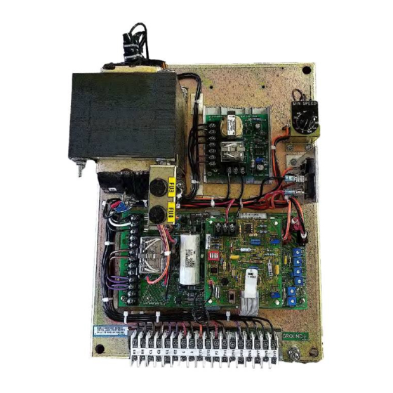
Torque Limit Modification PCB 15-444-2
Modification PCB Mounting
If you have purchased a complete controller this section may be passed over and you may proceed to
General Description.
1. Place the Main PCB in front of you with the long dimension in a horizontal position and the
terminal strip to the left.
2. Remove the DIP switch by pulling it straight out of the receptacle, RECP 1. Then, peel the adhesive-
backed label off the other half of RECP 1.
3. Insert the arrow type locking head of the four nylon stand-offs supplied into the four 0.188"
diameter holes in the main PCB and press in. The tabs will snap out to lock the stand-offs
permanently in position.
4. Hold the modification PCB assembly over the stand-offs with the ribbon connector toward you
and insert the ribbon connector plug into RECP 1. Be careful to see that all 16 pins are started
properly into the receptacle before pressing the plug in.
5. Align the holes in the modification PCB assembly over the stand-offs and press over the tapered
posts until the locking flanges snap out to lock the board in position.
General Description
For some variable speed drive application, it is necessary to limit the torque available to a machine in
order to prevent damage to the machine itself or its process. The Torque Limit modification provides an
"override" feedback signal which indirectly limits the induction motor torque (current) to a preset
7
