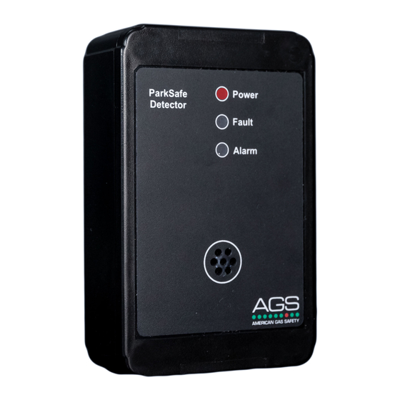
AGS Parksafe Control Panel 설치 및 운영 매뉴얼 - 페이지 8
{카테고리_이름} AGS Parksafe Control Panel에 대한 설치 및 운영 매뉴얼을 온라인으로 검색하거나 PDF를 다운로드하세요. AGS Parksafe Control Panel 16 페이지. Ventilation control panel
AGS Parksafe Control Panel에 대해서도 마찬가지입니다: 설치 및 운영 매뉴얼 (16 페이지), 설치 운영 및 유지보수 (16 페이지), 설치, 운영 및 유지보수 매뉴얼 (20 페이지)

Installation & Operation Manual
Creating a Detector Chain
Up to 16 Parksafe Detectors can be connected, chained in a parallel 'daisy chain' method up to
approx. 500 yards from the panel depending on chain configuration, wire type for power and
condition. Any other way may cause issues or damage to the overall system.
Remember to individually ID each connected detector by configuring the ID switches on the circuit
boards. Make a plan and/or map of the location of all detectors for tracing and locality purposes.
It is recommended that the cable of same color should be used to connect all [D+] terminals
together and similarly cable of same color to be used to connect all [D-] terminals together.
**Split chain example.
**Where connections may exceed 500 yards from one control panel – contact your supplier!
Remember to ID your detector!
120 ohm Termination Resistance
Signal communication issues may occur where the bus length is too long, high baud rates are used
or signal reflections are occurring. To avoid this, terminating at each end of a chain may help the
quality of the data signal by turning on the 120ohm terminal resistor switch.
Split chain
For more information refer to your Parksafe detector manual.
Access Configuration Settings
On the front display circuit board you'll find a SETTINGS switch – when switched on, the screen will
display the settings menu – you can now configure your Parksafe system.
When changes have been made – turn the settings switch off and the panel will restart!
AGS Parksafe Panel - IOM Iss: 6 10-20
**Single chain example
Single chain
Parksafe
8
