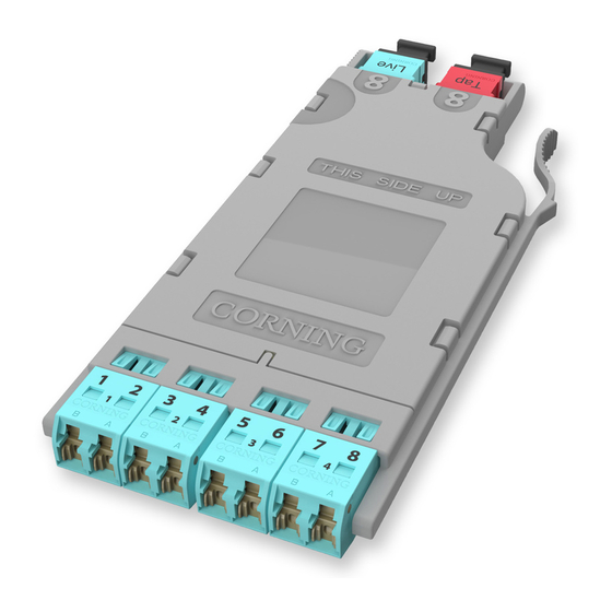
CORNING EDGE8 LC-MTP 설치 및 테스트 - 페이지 7
{카테고리_이름} CORNING EDGE8 LC-MTP에 대한 설치 및 테스트을 온라인으로 검색하거나 PDF를 다운로드하세요. CORNING EDGE8 LC-MTP 8 페이지. Tap module

8.3
Referencing is now complete. Move the Light Source and RJ1 to the front of the Tap module;
move M2, RJ3, and the LC adapter to the end of the Tap harness; and move M1 and RJ2 to
the EDGE8™ modules at the far end of the system (See Figure 11).
IMPORTANT: From this step on, do NOT disconnect the connectors on either the Light Source or
meter port adapters.
9.
Testing EDGE8 LC-MTP Tap Modules
9.1
Table 2 provides a complete guide to the testing sequence for testing with the light source at the
Tap module "A" ("Near end") and a meter at Module "B", or the "Far end" of the system shown in
Figure 11.
Source LC Position at "A"
A-2
A-4
A-6
A-8
Table 2: Testing Sequence with Light Source at the Tap Module
9.2
To begin testing a Tap module (Figure 11):
Step 1:
Install the Light Source/RJ1 LC connector into LC number 2 port of the Tap module.
Step 2:
Install RJ2's LC connector into the number 1 port of the EDGE8 module (Module "B"
in Figure 11).
Step 3:
Install LC connector number 1 from the Tap port test harness into the LC adapter on
the end of RJ3.
Step 4:
Save or record the first fiber's measurements. The reading will be the total system
loss.
"Near end"
multimode only
RJ1
EDGE8 Tap Module "A"
Do NOT
disconnect
Light
Source
HPA-0757-EDGE8
STANDARD RECOMMENDED PROCEDURE 003-137-AEN | ISSUE 1 | JANUARy 2017 | PAGE 7 OF 8
Module "B" LC Position
B-1
B-3
B-5
B-7
Link under test
Tap port test harness
1
RJ3
0.00 dB
M2
Meter no. 2 -TAP Port Test Harness
"Far end"
EDGE8 Module "B"
Do NOT
disconnect
Do NOT
disconnect
1
3
5
7
RJ2
0.00 dB
M1
Figure 11
