CORNING EDGE8 LC-MTP 설치 및 테스트 - 페이지 8
{카테고리_이름} CORNING EDGE8 LC-MTP에 대한 설치 및 테스트을 온라인으로 검색하거나 PDF를 다운로드하세요. CORNING EDGE8 LC-MTP 8 페이지. Tap module
9.3
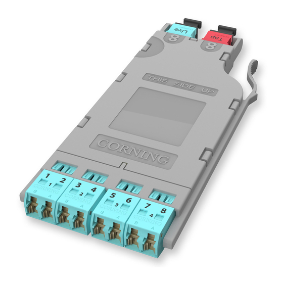
Table 3 provides a complete guide to the testing sequence for testing with the Light Source at
the "B" module ("Far end") and a meter at Tap module "A" ("Near end" ) of the system as shown
in Figure 12.
Source LC Position at "B"
B-2
B-4
B-6
B-8
Table 3: Testing Sequence with Light Source at the "B" Module
9.4
To test the odd-numbered ports at the front of the Tap Module, switch the "Near" and "Far"
locations of the Light Source/RJ1 and M1/RJ2. At the end of the Tap cable assembly, move
the LC adapter on M2/RJ3 to connector number 2 (Figure 12).
9.5
To complete the testing of the first Tap module, save or record each fiber's measurements as
you follow the sequence shown in Table 3.
9.6
Repeat the steps in this section on the remaining Tap modules.
"Near end"
RJ2
EDGE8 Tap Module "A"
0.00 dB
M1
HPA-0761-EDGE8
Corning Optical Communications LLC • PO Box 489 • Hickory, NC 28603-0489 USA
800-743-2675 • FAX: 828-325-5060 • International: +1-828-901-5000 • www.corning.com/opcomm
Corning Optical Communications reserves the right to improve, enhance, and modify the features and specifications of Corning Optical Communications products
without prior notification. A complete listing of the trademarks of Corning Optical Communications is available at www.corning.com/opcomm/trademarks. All other
trademarks are the properties of their respective owners. Corning Optical Communications is ISO 9001 certified. © 2017 Corning Optical Communications. All
rights reserved.
STANDARD RECOMMENDED PROCEDURE 003-137-AEN | ISSUE 1 | JANUARy 2017 | PAGE 8 OF 8
Meter no.1 LC Position at "A"
A-1
A-3
A-5
A-7
Link under test
Tap port test harness
RJ3 and adapter
2
8
0.00 dB
M2
Meter no. 2 -TAP Port Test Harness
2
4
6
8
EDGE8 Module "B"
"Far end"
multimode only
Light Source
Figure 12