AQC MAXIVIBE AMV-1140 소유자 매뉴얼 - 페이지 9
{카테고리_이름} AQC MAXIVIBE AMV-1140에 대한 소유자 매뉴얼을 온라인으로 검색하거나 PDF를 다운로드하세요. AQC MAXIVIBE AMV-1140 20 페이지.
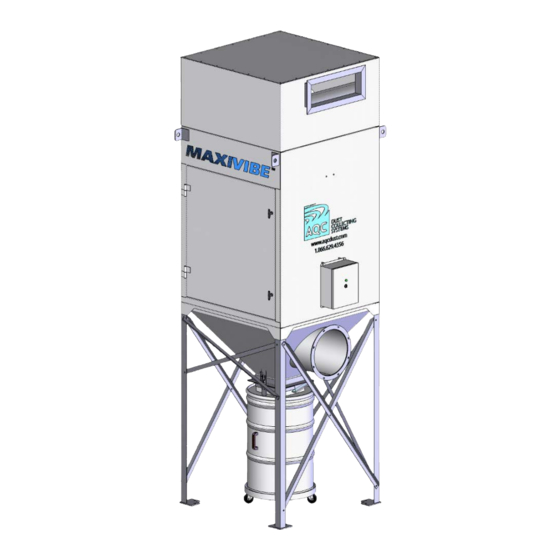
Shaker type dust collector
9
ELECTRICAL CONNECTIONS
The collector control panel controls the fan and the motorized shaker system.
The control panel may be installed directly on the MAXIVIBE unit, either the unit is located inside
or outside of the building or it may also be remote.
1. Using the electrical diagram supplied with the control panel, carry out the electrical
connection from the breaker (supplied by customer) to the control panel.
2. With double or triple MAXIVIBE collectors, the control panel is not wired to the fan motor
assembly when shipped. The control panel is although pre-wired when shipped. Connect the
control panel to the motor.
3 . Apply electrical power to the control panel and verify time delays T1 and T2. Refer to the
Maintenance section, under control panel for instructions on time delay adjustments.
4 . Check for proper motor rotation.
Figure 4 shows the operation with a typical starter equipped with an automatic shaker system :
When the selector is in "MANUAL" position, the fan is on. When the selector is in "OFF" position,
the fan stops, T2 runs its time delay, T3 then starts its delay for the shaker motor operating time.
You must switch the selector back to "ON" to restart the fan and the automatic cycle. When the
selector is in "AUTO" position, the fan starts only if the exterior connections complete the circuit.
Then, T2 runs its time delay, T3 then starts its delay for the shaker motor operating time.
WARNING!
The electrical connection must be performed by a certified
electrician and by following the local building rules and
regulations. For safety measure, disconnect all electrical
power prior to installation.
9