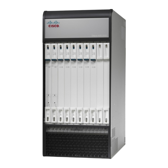
Cisco ASR 5500 설치 매뉴얼 - 페이지 8
{카테고리_이름} Cisco ASR 5500에 대한 설치 매뉴얼을 온라인으로 검색하거나 PDF를 다운로드하세요. Cisco ASR 5500 31 페이지.
Cisco ASR 5500에 대해서도 마찬가지입니다: 설치 절차 개요 (6 페이지)

MIO Interface Activity LED States
Table 7: MIO Interface Link LED States
Color
Green
None
MIO Interface Activity LED States
The Activity LED associated with a 1000Base-T (management) or 10 Gigabit Ethernet port on an
MIO/UMIO/MIO2 daughter card (subscriber traffic) indicates the presence of traffic on the network link.
This LED should be green when data is being transmitted or received over the interface.
The possible states for this LED are described in the following table. If the LED is not green, use the
troubleshooting information in the table to diagnose the problem.
Table 8: MIO Interface Activity LED States
Color
Flashing Green
None
Checking the LEDs on the DPC
Each DPC/UDPC or /DPC2/UDPC2 is equipped with status LEDs as listed below:
• Run/Fail
• Active
• Redundancy
Troubleshooting
8
Description
Link is up
No power to card.
OR
Link is down.
Description
Traffic is present on the link
No traffic is present on the link
Troubleshooting
Troubleshooting
None needed.
NOTE: This LED will not indicate the
presence of a network link until the
interface parameters are set during the
software configuration process.
Verify that the Run/Fail LED is green. If
so, the card is receiving power. If it is off,
refer to
MIO Run/Fail LED States, on page
4
for troubleshooting information.
Verify that the interface is cabled properly.
Verify that the device on which the
interface is located is cabled and powered
properly.
Troubleshooting
None needed.
None needed if there is no activity
on the link. Prior to interface
configuration, this is normal
operation.
