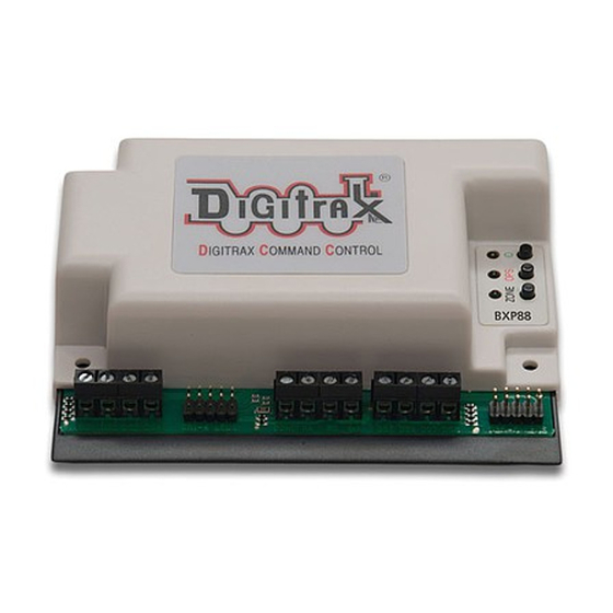
Digitrax BXP88 사용 설명서 - 페이지 14
{카테고리_이름} Digitrax BXP88에 대한 사용 설명서을 온라인으로 검색하거나 PDF를 다운로드하세요. Digitrax BXP88 16 페이지.

ty for a track detection section. Many detection problems are related to wiring
problems or poor connections to the detection section rather than to the actual
BXP88. By using the display array, you can eliminate the wiring issues from the
equation and be sure that the BXP88 is set up correctly.
Remember, if the zone power is OFF, the occupancy LEDs should be set up so
that they will be on to be sure that signaling systems or a CTC/dispatcher will see
the detection section in its most restricted aspect.
12.1 LocoNet Debug
The BXP88 reports information to LocoNet, so be sure that the connection is
working. In normal operations the red "OPS" LED will blink ON briefly when
valid incoming LocoNet messages are seen, confirming a good LocoNet network
connection. The BXP88 will blink the ZONE led green when a state message is
sent by the BXP88 to LocoNet.
12.2 Analog Locomotives
Analog Locomotive are not compatible with the BXP88, all locomotives must be
equipped with a DCC decoder.
13.0 Using a Test Transponder for debugging
You can use a Test Transponder as follows:
1.
Use transponder capable decoder set up with a 470 ohm resistor between the
blue and white leads. This removes any lamp issues from initial transpon-
ding tests. The motor leads can be left unconnected/insulated and all other
leads except the red/black track connections should be insulated. Set CV61
to a value of 02 to enable transponding.
2.
Ensure the BXP88 is properly connected to your Command Station/Booster
via Rail A and Rail B connections. Connect the BXP88 to your Command
Station/Booster using a Known good LocoNet cable. Connect an LT5 to the
"DS1-4 LED" header.
3.
Use the first Detection Section (DS1), hook RAX to the decoder RED lead and
DS1 to the decoder BLACK lead.
4.
Power up the System and the BXP88 connected to the test decoder. Turn on
Track Power and select the decoder's address in a throttle. (Decoder factory
defaults are Address 03).
5.
DS 1 LED will blink steadily indicating that a valid transponder with that
address is being detected in that transponding zone.
14.0 FCC Information
Radio or TV Interference: (this information is MANDATED by the FCC) This
equipment has been tested and found to comply with the limits for a Class B
digital device, pursuant to part 15 of the FCC rules. These limits are designed to
provide reasonable protection against harmful interference when the equipment
© 2017 Digitrax, Inc.
— 14 —
www.digitrax.com
