Cisco ONS 15454 설치 - 페이지 8
{카테고리_이름} Cisco ONS 15454에 대한 설치을 온라인으로 검색하거나 PDF를 다운로드하세요. Cisco ONS 15454 32 페이지. Four-shelf and zero-shelf bay assembly
Cisco ONS 15454에 대해서도 마찬가지입니다: 설치 지침 매뉴얼 (22 페이지), 설치 (32 페이지), 포장 풀기 및 설치 (42 페이지), 포장 풀기 및 설치 (40 페이지)
NTP- A5 Install the EIAs
NTP-A5 Install the EIAs
Purpose
Tools/Equipment
Prerequisite Procedures
Required/As Needed
Onsite/Remote
Security Level
Always use the supplied ESD wristband when working with a powered ONS 15454. Plug the wristband
Caution
cable into the ESD jack located on the lower-right outside edge of the shelf assembly.
EIAs are normally factory installed. Verify that the correct EIA is installed on the shelf assembly. If not,
Note
install the correct EIA.
You do not need to power down the shelf before removing or installing an EIA. An in-service upgrade
Note
of one EIA (A side or B side) is possible if all electrical traffic (DS-1, DS-3, DS3XM-6, and EC-1) is
being carried on the other side.
Complete the
Step 1
are locking connectors; the high-density BNC provides access to every port on every card.
Step 2
Complete the
up to 96 DS-3 circuits on each side of the ONS 15454.
Step 3
Complete the
every port on every card using more space and efficient cabling.
Complete the
Step 4
exclusive to DS-1 cables.
Complete the
Step 5
EIAs allow you to use high-density electrical cards. The UBIC-V EIAs provide SCSI connectors.
Complete the
Step 6
(horizontal) EIAs allow you to use high-density electrical cards. The UBIC-H EIAs provide SCSI
connectors.
Cisco ONS 15454 Procedure Guide, Release 8.5.1
1-8
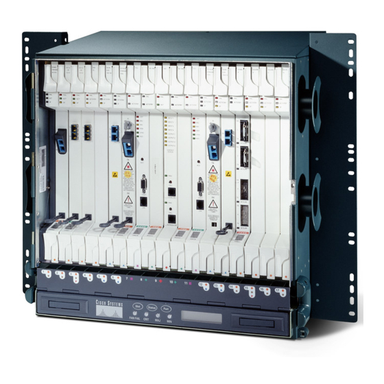
This procedure describes how to install electrical interface assemblies
(EIAs). Typically, an EIA panel is installed on the backplane during
manufacturing, but EIA panels can be ordered separately. Refer to the
Cisco ONS 15454 Reference Manual for descriptions of the EIAs.
#2 Phillips screwdriver
Medium slot-head screwdriver
Small slot-head screwdriver
Perimeter screws (9)
Inner screws (12)
Backplane cover screws (5)
EIA card (SMB, BNC, AMP Champ, UBIC-V, UBIC-H, MiniBNC)
NTP-A4 Remove the Backplane Covers, page 1-7
Required if the node will use electrical signals
Onsite
None
"DLP-A12 Install a BNC or High-Density BNC EIA" task on page 17-12
"DLP-A373 Install a MiniBNC EIA" task on page 20-56
"DLP-A13 Install an SMB EIA" task on page 17-15
"DLP-A14 Install the AMP Champ EIA" task on page 17-16
"DLP-A190 Install a UBIC-V EIA" task on page 18-59
"DLP-A399 Install a UBIC-H EIA" task on page 20-108
Chapter 1 Install the Shelf and Backplane Cable
as needed. BNCs
as needed. The MiniBNC allows
as needed. SMBs allow you to access
as needed. AMP Champs are
as needed. The UBIC-V (vertical)
as needed. The UBIC-H
78-18537-01