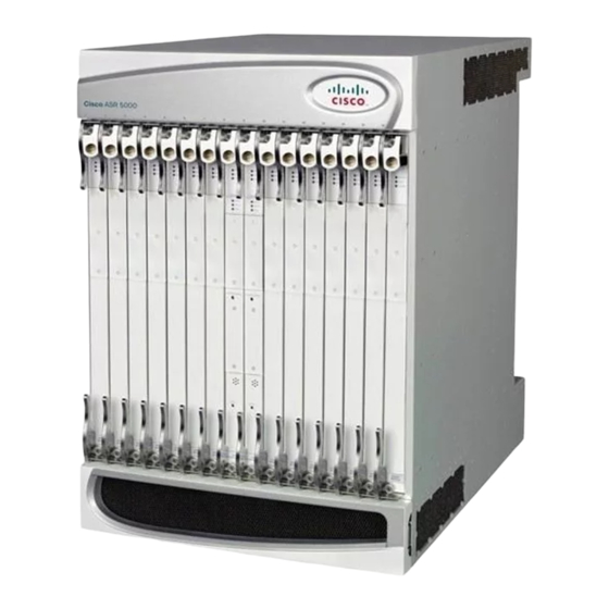
Cisco ASR 5000 설치 매뉴얼 - 페이지 23
{카테고리_이름} Cisco ASR 5000에 대한 설치 매뉴얼을 온라인으로 검색하거나 PDF를 다운로드하세요. Cisco ASR 5000 33 페이지. Applying power and verifying the installation
Cisco ASR 5000에 대해서도 마찬가지입니다: 설치 매뉴얼 (18 페이지), 설치 절차 (8 페이지), 설치 매뉴얼 (37 페이지)

Troubleshooting
In the event that an issue arises that is not severe enough for the system to perform an automatic migration,
a manual migration can be invoked. Follow the instructions below to manually initiate a packet processing
card migration. These instructions assume you are at the root prompt for the Exec mode.
Step 1
Initiate a manual packet processing card migration by entering the following command:
host_name
[local]
You will receive the following prompt:
Are You Sure? [Yes|No]:
For a complete description of the above command, see the Exec Mode Commands chapter of the Command line Interface
Reference.
Step 2
Press Y to start the migration.
Step 3
Verify that the migration was successful by entering the following command.
host_name
[local]
Check the entry in the Oper State column next to the packet processing card that was just migrated from. Its state should
be Standby. The state of the packet processing card migrated to should be Active.
Manually Initiating a Line Card or SPIO Switchover
Ethernet line cards are installed in the half-height slots at the rear of the chassis. This design allows for two
half-height line cards to be installed behind every application card (vertical redundancy). With two line cards
installed, booting their associated application card causes the card in the upper-rear chassis slot to automatically
be made active while the card in the lower-rear chassis slot will automatically be placed in standby mode. In
the event that the active card experiences a failure, the system will automatically switch traffic to the standby
card in the lower slot.
The XGLC is a full-height card that supports 1:1 side-by-side redundancy. Side-by-side (horizontal) redundancy
allows two XGLC cards installed in neighboring slots to act as a redundant pair. Side-by-side pair slots for
the XGLC are: 17-18, 19-20, 21-22, 23-26, 27-28, 29-30, and 31-32. If the XGLCs are not configured for
side-by-side redundancy, they run independently without redundancy.
When configured for side-by-side redundancy, The XGLC is referenced only by the upper slot number (17
through 23, 26 through 33); the lower slot number is not recognized. All other configuration commands work
as if the side-by-side slots were top-bottom slots. Configuration commands directed at the bottom slots either
fail with errors or are disallowed.
In the event that a SPIO experiences a failure, the system will automatically switch traffic to the redundant
SPIO installed behind the redundant SMC.
In the event that an issue arises that is not severe enough for the system to perform an automatic switchover,
a manual switchover can be performed. Follow the instructions below to manually initiate a line card or SPIO
switchover. These instructions assume you are at the root prompt for the Exec mode:.
Step 1
Initiate a manual line card or SPIO migration by entering the following command:
host_name
[local]
card migrate from original_slot# to final_slot#
#
show card table
#
card switch from slot# to slot#
#
Manually Initiating a Line Card or SPIO Switchover
ASR 5000 System Administration Guide, StarOS Release 21.2
23
