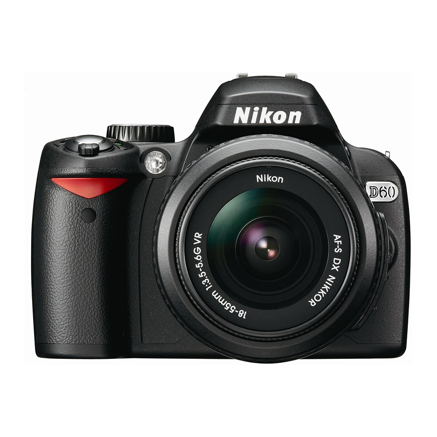
Nikon D90 - Digital Camera SLR 사용자 설명서 - 페이지 16
{카테고리_이름} Nikon D90 - Digital Camera SLR에 대한 사용자 설명서을 온라인으로 검색하거나 PDF를 다운로드하세요. Nikon D90 - Digital Camera SLR 26 페이지. Focal digital camera
Nikon D90 - Digital Camera SLR에 대해서도 마찬가지입니다: 브로셔 및 사양 (9 페이지), 운영 매뉴얼 (20 페이지), 사양 (2 페이지), 체크리스트 및 운영 매뉴얼 (25 페이지), 매뉴얼 (28 페이지), 방법 (6 페이지), 매뉴얼 (30 페이지)

SW1 Switchboard
J1 connecter - Manual mode
the digital data of modern cameras is incompatible with conventional TTL
strobes and as 'old style' strobes might use a tension that is too high for
modern cameras and might damage the camera circuitry.
J1 connecter - iTTL or eTTL mode
as the strobes will need all the data on all the lines. Please note that in this
case only one strobe can be connected to the housing as most of these
strobe systems require a master and slave strobe. The master strobe will
be connected to the housing while the slave strobe will be connected to the
master strobe. In case Canon eTTL strobes are used, all 6 lines are required
and a 6-pin strobe connection needs to be installed on the housing.
J1 connecter - iTTL or eTTL mode + Manual mode
eTTL compatible strobe on SW1 have to switched on while all the connec-
tors of the non iTTL or eTTL compatible strobe have to switched off.
Hugyfot Housing for
SW1 Switchboard: 1 = Q signal on J4 connecter
When the camera hot shoe is connected to J1 and
when strobes are used in manual mode we strongly
recommend that all the switches on SW1 are turned
off. In this case only X and ground will be used as
When the camera hot shoe is connected to J1 and
when fully iTTL or eTTL compatible strobes are used
(e.g. Nikon SB 800, Canon 580 EX, Subtronic dttl,
...) all the switches on SW1 have to be switched on
When the camera hot shoe is connected to J1 and
when 1 fully iTTL or eTTL compatible strobe is used
in combination with 1 non iTTL or eTTL compatible
strobe, then all the connectors of the fully iTTL or
Nikon D90
2 = Q signal on J3 connecter
3 = SP signal on J4 connecter
4 = SP signal on J3 connecter
5 = RDY signal on J4 connecter
6 = RDY signal on J3 connecter
16
User manual
