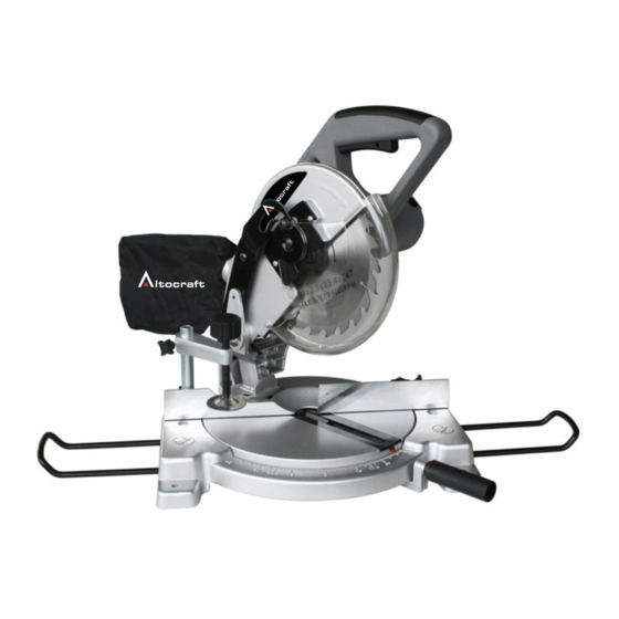
Altocraft 240-2087 운영자 매뉴얼 - 페이지 7
{카테고리_이름} Altocraft 240-2087에 대한 운영자 매뉴얼을 온라인으로 검색하거나 PDF를 다운로드하세요. Altocraft 240-2087 10 페이지. 8-1/4 inch compound miter saw

MAINTENANCE
ALIGNING MITER AND BEVEL
Miters and bevels have been set at the factory. However, use may effect settings.
Please use the following procedures when your tool needs adjustments.
Miter Angle
1. Set the bevel angle at 0 degree.
2. Loosen the locking handle.
3. Depress the miter detent spring lever.
4. Turn the saw table so that the arrow in the kerf plate points to 0 degree, then
move the table slightly clockwise and counter-clockwise and let the miter de-
tent spring lever fit into the groove (it doesn't matter if needle doesn't indicate 0
degree ).
5. Loosen the four hex bolts behind the fence with the blade socket wrench.
6. Lower the saw head and lock it in place with the head lock button.
7. Use the clear plastic setup triangle to check that the saw blade and the fence
are square. Move the fence a few millimeters to achieve this if
necessary.
8. Tighten the hex bolts in the fence firmly.
9. Confirm that the arrow in the kerf plate points to 0 degree. If not, loosen the
two screws in the bottom of the miter detent spring lever and adjust accord-
ingly.
Bevel Angle
A. Vertical stop: 0 degree adjustment
1. Lower saw head to lowest position and lock it with the head lock button.
2. Loosen the bevel lock handle on the back of the saw.
3. Check that the blade is perpendicular to the table as measured by the clear
plastic setup triangle. If not :
Use an open-end wrench to loosen the hex lock nut at the back left side
a.
of the table.
b. Turn the bolt counter-clockwise and the 0 point moves left, closing the angle.
Turning it clockwise moves the 0 point to the right, opening the angle.
c. When you have established the vertical stop correctly, tighten the lock nut
to hold the setting.
d. Make sure that the needle points to 0 degree on the scale. If not, loosen
the screws and adjust the needle.
B. Bevel stop: 45 degrees adjustment
1. Lower the saw head to lowest position and lock it with the head lock button.
2. Loosen the bevel lock handle on the back of the saw.
3. Check that the blade is at 45 degrees to the table as measured by the clear
plastic setup triangle. If not :
a. Use an open-end wrench to loosen the hex lock nut at the back left side
of the table.
b. Turn the bolt clockwise and the 45 degrees point moves left, opening the angle.
Turning it counter-clockwise moves the 45 degrees stop to the right, closing
the angle.
c. When you have established the 45 degrees stop correctly, tighten the lock nut
to hold the setting.
d. Make sure that the needle points to 45 degrees on the scale. If not, loosen the
screws and adjust the needle.
