Ashly MQX-2310 운영 매뉴얼 - 페이지 6
{카테고리_이름} Ashly MQX-2310에 대한 운영 매뉴얼을 온라인으로 검색하거나 PDF를 다운로드하세요. Ashly MQX-2310 13 페이지. Graphic equalizer
Ashly MQX-2310에 대해서도 마찬가지입니다: 브로셔 (1 페이지), 운영 매뉴얼 (16 페이지), 운영 매뉴얼 (12 페이지), 기술 노트 및 사양 (2 페이지)

Page - 6
Introduction - 4
Physical Description
MQX Equalizers – 5
The MQX-2310 is 2RU, and weighs 11 pounds.
Connectors & Cables – 5
Physical Description - 6
Front Panel
Rear Panel
Installation – 7
Typical Applications - 8
Troubleshooting - 9
Dimensions - 9
Specifications - 10
Warranty - 11
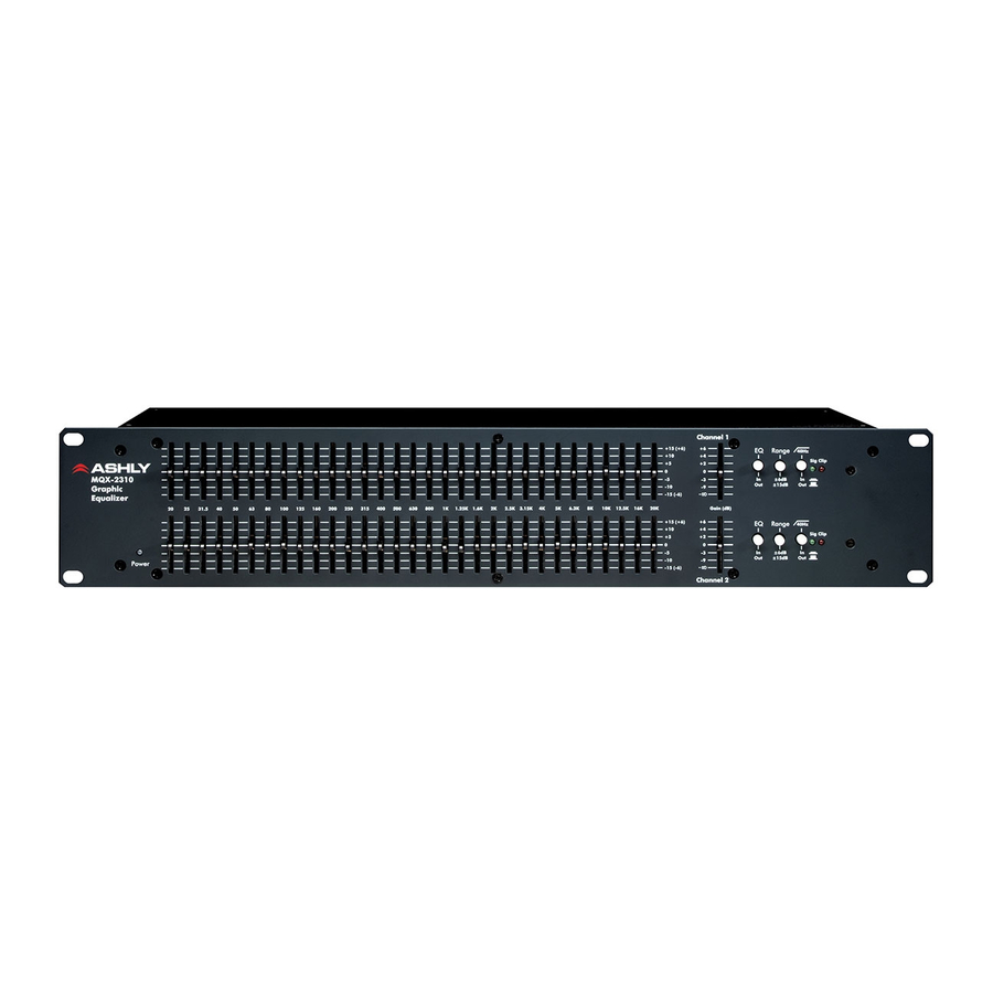
MQX-2310 Front Panel
1.
Power LED – Displays power on or off.
2.
Equalization - The individual equalization
faders adjust the gain or loss at each filter
frequency. There are 31 of these faders per
channel on the MQX-2310. By adjusting a
combination of faders, an overall frequency
response can be developed and the physical
position of the faders will give an approximate
visual indication of this response.
3.
Gain - The gain control adjusts the overall gain
of the equalizer when the EQ switch is "in". It is
generally used to compensate for level
changes due to the equalization process, but
can also adjust overall system level and gain
structure. Overall gain with this control is from
+6dB to -∞.
4.
Signal Present LED – A green LED indicates
when input signal to the equalizer is above
–20dBu. EQ or Gain settings have no effect on
this indicator, as it only tells you the level of
signal applied to the equalizer.
5.
Clip Indicator LED – The red Clip LED turns
on when any signal within the audio path
MQX-2310 Rear Panel
1.
Power – Switches the unit power on or off
2.
Inputs - For unbalanced inputs, the signal
should be on the + connection and the -
connection tied to ground. A mono 1/4" plug
used as an unbalanced connection will
automatically be grounded. When using a
stereo plug, XLR connector, or euroblock for an
unbalanced signal, the (-) input connection
MUST be tied to ground.
Operator Manual – MQX-2310 Equalizer
Copyright© 2012 – Ashly Audio Inc.
exceeds +19dBu. Clipping can be detected at
the input stage, gain stage, or equalizer output.
6.
Range Switch - This switch selects the
operating range of the individual equalization
faders between 15dB and 6dB. The 15dB
settings should be used when this much
equalization is needed. The 6dB setting allows
finer resolution on the fader settings.
7.
EQ In/Out Switch - This switches the Graphic
Equalization and gain adjustments, allowing the
effect of any equalization to be compared to a
"flat" response. This switch does not defeat the
High-pass filter.
8.
High-Pass Filter - The high-pass filter can be
used to supplement the frequency response
achieved by the bandpass filters. Its function is
to "roll off" the response below a given
frequency eliminating subsonic interference like
wind noise or floor rumble. The high-pass
frequency is fixed at 40Hz with an 18dB/Oct
slope.
3.
Ashly Servo-Balanced Output - This output
circuit is an active output which maintains a
constant output level between the (+) and (-)
output terminals, regardless of either terminal
being connected to ground. This servo-
balanced output provides an unchanged signal
without regard to ground.
