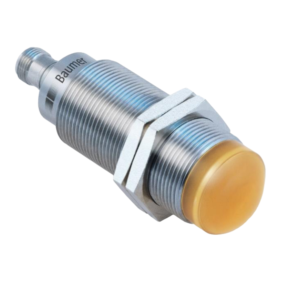
Baumer IO-Link RR30 Instruction Manual - Page 17
Browse online or download pdf Instruction Manual for Accessories Baumer IO-Link RR30. Baumer IO-Link RR30 40 pages. Radar sensor

To avoid false switching operations in case of an object which is not 100% stable to detect over the
-
whole length
To suppress short losses of a proper signal due to known disturbances such as the wheel of a mixer
-
To avoid bouncing.
-
To optimize the timing of the execution of a subsequent actor triggered by the output of the sensor.
-
To detect an unwanted gap size within a continuous flow of products.
-
Parameter name
Release Delay.SSC1 Time
4.3.7.3 Minimal Pulse Duration
The minimal pulse duration defines the minimum time, the switching signal of the related SSC stays active or
inactive after the change of its status.
This parameter can be applied on
both slopes / active and inactive
-
positive slope / active (or inactive, if the logic is inverted as described in section 4.3.4)
-
negative slope / inactive (or active, if the logic is inverted as described in section 4.3.4)
-
When to apply?
To align the timing of the sensor to a slower PLC.
-
To avoid bouncing.
-
en_BA_RR30_IO-Link_V0.23.docx
13.01.2021/
Figure 20: Release Delay
Short Description
Sets / indicates the release delay
time in milliseconds for the
respective switching signal channel
(SSC).
17/40
Rights
Unit /
Allowed
values
rw
0 to 60000 ms
Default: 0 ms
Baumer Electric AG
Frauenfeld, Switzerland
