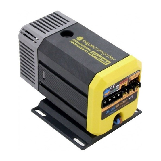
Aqua Computer AQUASTREAM XT USB User And Installation Manual - Page 7
Browse online or download pdf User And Installation Manual for Water Pump Aqua Computer AQUASTREAM XT USB. Aqua Computer AQUASTREAM XT USB 20 pages.
Also for Aqua Computer AQUASTREAM XT USB: User And Operating Manual (16 pages)

aqua
computer
7.4. Connector "aquabus/flow"
7.4. Connector "aquabus/flow"
7.4. Connector "aquabus/flow"
7.4. Connector "aquabus/flow"
Connector for communication with other Aqua Computer devices. For versions
Standard and Advanced, the connector "aquabus/flow" is configured as an
aquabus interface and can be used for instance to connect the pump to an op-
tionally available aquaero fan controller. For these variants, a flow sensor must
not be attached to this connector!
You can use the aquabus/speed signal cable included in delivery to connect the
pump controller board to a suitable connector of a compatible device, for ex-
ample an aquaero. USB and aquabus interface can be used at the same time,
however not all control options of the aquastream XT are available using the
aquabus interface.
If this connector is connected to an aquabus device, the port must not be con
If this connector is connected to an aquabus device, the port must not be con
If this connector is connected to an aquabus device, the port must not be con
If this connector is connected to an aquabus device, the port must not be con- - - -
figured as flow sensor input! Otherwise, the pump controller will be destroyed and
figured as flow sensor input! Otherwise, the pump controller will be destroyed and
figured as flow sensor input! Otherwise, the pump controller will be destroyed and
figured as flow sensor input! Otherwise, the pump controller will be destroyed and
all guarantees will be void!
all guarantees will be void!
all guarantees will be void!
all guarantees will be void!
For the Ultra variant, this connector can be configured for two different functions.
Default configuration of this connector is an aquabus interface. Using the aqua-
suite software, this connector can also be configured to be a flow sensor input.
Simultaneous use of the aquabus and flow sensor function is not possible! Please
see chapter 14.4. for details on configuring the desired function.
Flow sensor and special interconnecting cable are optional accessories and not in-
cluded in delivery.
Pin assignment:
Pin 1: GND
Pin 2: aquabus SDA / flow sensor +5 V
Pin 3: aquabus SCL / flow sensor signal
Compatible aquabus devices:
aquaero 5 XT (art. 53125 and 53089)
●
aquaero 5 PRO (art. 53090)
●
aquaero 5 LT (art. 53095)
●
Compatible flow sensors:
Flow sensor with 5.6 mm nozzle (art. 53061)
●
Flow sensor "high flow" (art. 53068)
●
Connection cable for flow sensor (art. 53027)
●
7.5. Connector "rpm"
7.5. Connector "rpm"
7.5. Connector "rpm"
7.5. Connector "rpm"
Depending on configuration, this header can be used as a generic speed signal.
The speed signal can be configured (using the aquasuite software, see chapter
13.1.) to be deactivated in case of an alarm condition for monitoring purposes.
For example, the aquabus/speed signal cable included in delivery can be used to
connect this header to the CPU fan header of the PC's motherboard and depend-
ing on the motherboard and BIOS settings, an automatic emergency shutdown
© 2007-2013
Aqua Computer GmbH & Co. KG
Gelliehäuser Str. 1, 37130 Gleichen
AQUASTREAM XT
- 7 -
