DFE SW6 Operating Instructions Manual - Page 13
Browse online or download pdf Operating Instructions Manual for Controller DFE SW6. DFE SW6 20 pages. Digital tension controller

2.4 AUTO TENSION SETPOINT AND MANUAL OUTPUT SETTING
Pressing or tapping the tension display area on
either the Analog Meter or Trend-line Graph
display will bring up "+" and "-" buttons (Fig. 13),
which are used to adjust the auto tension setpoint
by pressing or holding them down. Buttons used
to adjust numerical values are velocity sensitive,
meaning that the longer the button is depressed,
the faster values change.
Setpoint adjustments made in this manner apply
only to the mode displayed on screen at the time.
In other words, if the "+" and "-" buttons are used
in the Auto mode, no change is made to the
Manual output, and vice versa.
When adjusting the auto tension setpoint with
the "+" and "-" buttons in either the Analog Meter or Trend-line Graph display, the actual tension in white
characters is temporarily replaced with the auto tension setpoint in yellow characters. When the "+" and "-"
buttons fade away, the auto tension setpoint in yellow characters disappears and the tension in white
characters returns.
2.5 TAPER TENSION
In some cases where poor roll quality might result
from winding the entire roll at constant tension,
certain types of roll quality problems can be
avoided by reducing the tension as the diameter of
the roll increases from the core. This reduction is
known as Taper, and may be enabled at Menu >
Main Menu > Operator Menu > Configure Taper >
Taper Enable (Fig. 14). Because the tension
setpoint is constantly changing in this case, a new
control target has been established, called the
Dynamic Tension Setpoint.
The dynamic tension setpoint is the auto tension
setpoint, linearly reduced by the Taper
Percentage, going from core diameter to full roll
diameter. For example, with an auto tension
setpoint of 50 lbs, and the taper percentage set at
20%, the dynamic tension setpoint will be 50 lbs at
core, and decrease linearly to (100% - 20%) x 50
lbs = 40 lbs at full roll.
The taper percentage may be adjusted at Menu
> Main Menu > Operator Menu > Configure Taper
> Taper Percentage (Fig. 15). The dynamic
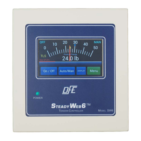
tension setpoint is identified on the momentary
tension display with a blue caret above the short
meter divisions (Fig. 16), and on the trend-line plot
as a line plot with an adjacent "T" (Fig. 17) which
moves up or down in the RH margin as the roll
diameter changes.
Figure 13 - ADJUSTING SETPOINT
Figure 14 - ENABLE TAPER TENSION
Figure 15 - SET TAPER PERCENTAGE
7
