Chromalox 2110 Instruction Manual - Page 2
Browse online or download pdf Instruction Manual for Temperature Controller Chromalox 2110. Chromalox 2110 20 pages.
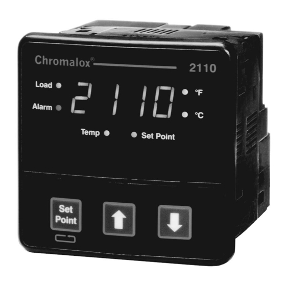
Table of Contents
Manual Sections
1
Quick Setup ........................................................................................................................ 1
2
Introduction ........................................................................................................................ 2
3
Installation and Wiring ...................................................................................................... 4
4
Adjusting Setpoint and Configuration ............................................................................. 8
5
Controller and Alarm Operation ..................................................................................... 11
6
Replacing Output Modules ............................................................................................. 12
7
Calibration ........................................................................................................................ 14
8
Specifications .................................................................................................................. 15
9
Troubleshooting ............................................................................................................... 17
1.1 Dip Switch Settings ........................................................................................................... 1
1.2 Establishing the Set Point ................................................................................................. 1
1.3 Adjusting the Set Point ...................................................................................................... 1
2.1 Front Panel Identification ................................................................................................... 2
2.2 Typical Application. ............................................................................................................ 2
2.3 Model Identification ........................................................................................................... 3
3.1 Default Dip Switch Settings ............................................................................................... 4
3.2 Removing Mounting Collars .............................................................................................. 4
3.3 Mounting Dimensions ........................................................................................................ 4
3.4 Mounting the 2110 ............................................................................................................ 4
3.5 Wiring Terminal Identification............................................................................................. 4
3.6 Thermocouple Connections with Shield ............................................................................ 6
3.7 Three-Wire RTD Connections with Shield ......................................................................... 6
3.8 Two-Wire RTD Connections .............................................................................................. 6
3.9 Control Output Wiring-R1 and S0 ..................................................................................... 7
3.10 Control Output Wiring-R3 ................................................................................................. 7
3.11 Control Output Wiring-V0 .................................................................................................. 7
3.12 Control Output Wiring-S1 and S2 ..................................................................................... 7
3.13 90-260 VAC Instrument Power Connections ..................................................................... 7
3.14 Alarm Connections ............................................................................................................ 7
4.1 Establishing the Set Point ................................................................................................. 8
4.2 Adjusting the Set Point ...................................................................................................... 8
4.3 Configuring 2110 ............................................................................................................... 8
4.4 Configuring 2110 ............................................................................................................... 8
4.5 Configuring 2110 ............................................................................................................... 8
4.6 Configuring 2110 ............................................................................................................... 8
4.7 Configuring 2110 ............................................................................................................... 8
4.8 Configuring 2110 ............................................................................................................... 8
6.1 Replacing Output Module ............................................................................................... 13
ii