Olympus BH2 Series Troubleshooting & Adjustment Manual - Page 32
Browse online or download pdf Troubleshooting & Adjustment Manual for Microscope Olympus BH2 Series. Olympus BH2 Series 46 pages. Phase contrast
Also for Olympus BH2 Series: Complete Teardown, Cleaning, And Reassembly (23 pages), Complete Teardown, Cleaning, And Reassembly (40 pages), Teardown, Cleaning And Reassembly (45 pages), Manual (6 pages), Installation Manual (9 pages)
D.
TROUBLESHOOTING (B2-BDS-3)
No. D-1
l.
Hints for Using
This Manual
This manual is written in the flowchart format.
Follow the arrow
mark to find out a defective
part.
The
numbers
and symbols like \H-lj
and
jw-2j indicate the numbers of
connector
and pin.
"Between
IH-11
and
IW-21"
means "Connect HOT to IH-lland GND to lw-21
when
measuring
with
a multimeter".
GND-+ A reference
voltage, OV, in an electronic circuit.
HOT -+ A
line to apply a supply
voltage.
The symbols like
®
and
@
mean "Jump to
®
and
@
in the same item".
The
symbols
®
and
@
mean "Proceed the work according to the
check
methods
®
and
@
given in the
same
item".
*
Be sure to
set up the unit before turning on the main switch.
A
terminal is exposed at
rn:=IJ
and I
W-2~
Measure at the exposed part
without removing.
The electrical
base for BHS is available in B2-BDS-2 and B2-BDS-3.
Refer
to the manuals for each model.
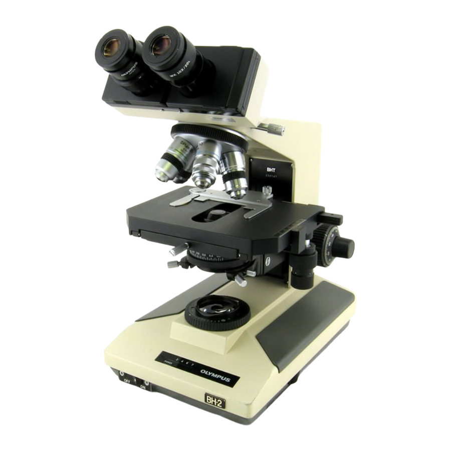
The difference in the
appearance
of the two models is shown below.
--------
B2-BDS-2
B2-BDS-3
LED
calor
Red
Green
Primary voltage
YES
NO
selector switch
lOOV
AB098800
AB615900
Nameplate
channel
AB099900
AB616100
200V
AB098900
AB6
1
6000
Channel
ABlOOOOO
AB616200
YES
The selector switch is
provided.
NO
The selector switch is not
provided.
The
nameplates
are compared on the next page.