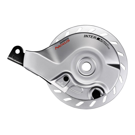
Shimano BR-IM35 Dealer's Manual - Page 15
Browse online or download pdf Dealer's Manual for Bicycle Accessories Shimano BR-IM35. Shimano BR-IM35 27 pages. Hub roller brake

- 1. Table of Contents
- 1. Important Notice
- 2. To Ensure Safety
- 3. Installation
- 3. List of Tools to be Used
- 3. Installation of the Lever
- 3. Installing the INTER M Brake to the Hub Body
- 3. Installation of the Hub to the Frame
- 3. Installation of the Brake Cable
- 4. Adjustment
- 4. Adjusting the Brake Cable
- 5. Maintenance
- 5. Applying Grease
INSTALLATION
Installation of the hub to the frame
Front side
<For quick release type>
1
(A)
(b)
(C)
2
<For nut type>
(F)
(E)
(e)
Check that the front brake unit (A) is
firmly secured to the hub with the
brake unit fixing nut (B).
(a)
(a)
(B)
Check that the hub axle (C) is touching
(c)
the back of the dropout, and that the
end of the brake arm is protruding 11
(D)
mm or more from the brazed-on
bracket (D) of the front fork. Check
also that the wheel is firmly secured to
the frame with the quick release or the
hub nut.
If the wheel is not installed properly, it
may come off the frame, which could
result in a serious accident when
riding.
(d)
(b)
(c)
(d)
Check that the front brake unit (F) is
firmly secured to the hub body with
the hub nut (E).
(e)
With notches (The side with
notches is the front.)
Touching
11 mm or more
For quick release type:
Secure the cam lever of the quick
release firmly.
Without notches
15
(A)
Brake unit
(B)
Brake unit fixing nut
Tightening torque
15 - 20 N·m
(C)
Hub axle
(D)
Brazed-on bracket
Cam lever tightening torque
5 - 7.5 N·m
(E)
Hub nut
(F)
Brake unit
Tightening torque
20 - 25 N·m
