Siemens SINAMICS G120 Compact Operating Instructions - Page 19

Browse online or download pdf Compact Operating Instructions for Industrial Equipment Siemens SINAMICS G120. Siemens SINAMICS G120 32 pages. Using blocksize converters in marine applications
Also for Siemens SINAMICS G120: Getting Started (46 pages), Operating Instructions Manual (32 pages), Getting Started (30 pages), Hardware Installation Instructions (2 pages), Installation Instructions And Owner's Manual (2 pages), Installation Instructions (2 pages), Installation Instructions (2 pages), Manual (42 pages), Getting Started (50 pages), Device Manual (34 pages), Quick Install Manual (2 pages), Application Description (50 pages), Compact Operating Instructions (2 pages), Manual (31 pages), Applications Manual (34 pages), Compact Operating Instructions (2 pages), Compact Operating Instructions (2 pages)
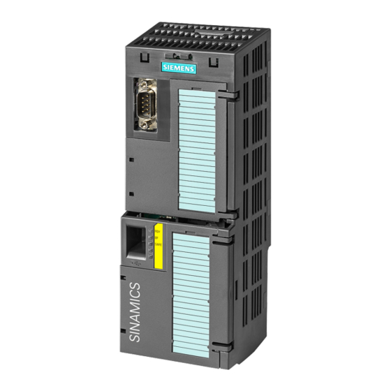
Siemens SINAMICS G120 Compact Operating Instructions
4.2

Commissioning with BOP-2 operator panel

Plugging on an operator panel
Procedure
To plug an Operator Panel on the Control Unit, proceed as follows:
1. Locate the lower edge of the Operator Panel into the matching recess
of the Control Unit.
2. Press the Operator Panel onto the inverter until you hear the latching
mechanism engage.
You have plugged an operator panel onto the Control Unit.
The operator panel is ready for operation when you connect the inverter
to the power supply.
4.2.1

Basic commissioning with BOP-2

Carry out basic commissioning
Preconditions
Procedure
Proceed as follows to carry out basic commissioning:
1.
2.
3.
4.
5.
CU240B-2 and CU240E-2 Control Units
Compact Operating Instructions, 04/2015, A5E35792002B AA
• The power supply is switched on.
• The operator panel displays setpoints and actual values.
Press the ESC key.
Press one of the arrow keys until the BOP-2 displays the "SETUP" menu.
In the "SETUP" menu, press the OK key to start basic commissioning.
If you wish to restore all of the parameters to the factory setting before
the basic commissioning:
4.1.
Switch over the display using an arrow key: nO → YES
4.2.
Press the OK key.
When selecting an application class, the inverter assigns the appropri-
ate default settings to the motor control:
STANDARD
DYNAMIC
EXPERT
4.2 Commissioning with BOP-2 operator panel
→ Standard Drive Control (Page 21)
→ Dynamic Drive Control (Page 23)
The approach is described in the operating instructions
→ Manuals for your inverter (Page 31)
Commissioning
19