3D Systems Touch User Manual - Page 11
Browse online or download pdf User Manual for Medical Equipment 3D Systems Touch. 3D Systems Touch 19 pages. 3d stylus hands on design
Also for 3D Systems Touch: User Manual (17 pages)

4
GETTING TO KNOW THE TOUCH
4
TOUCH COMPONENTS
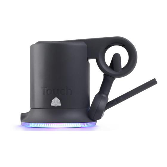
The picture below labels the parts of the Touch device.
USB Connection
LED (LIGHT) RING INDICATORS
The LED ring at the base of the Touch will display a different color light depending on the status of the Touch.
•
Blue - Power is on, but not communicating with application
- Displays blue after the power supply is plugged in
- Displays blue if GTDD (Geomagic Touch Device Driver) is not installed
- Displays blue if Geomagic Touch Setup utility has not been run
- Displays blue when no haptic enabled application is open
•
Blinking Blue - Communicating with application, Touch needs to be calibrated
- Displays blinking blue when the Touch needs to be calibrated by placing the stylus pen in the inkwell
- Displays blinking blue when the Touch needs to be calibrated by opening the Geomagic Touch Diagnostic utility and calibrating
White - In inkwell for calibration, communicating with application, Force feedback inactive
•
- Displays white when the stylus is in the inkwell during and after calibration. The Touch is communicating with the open
application, but force feedback is not being used.
•
Green - Calibrated, communicating with application, Force feedback is active
- Displays green when the Touch is calibrated and is communicating with an open application. The Touch is using force feedback.
NOTE: The orb stylus will always display white.
3D Systems, Inc.
LED ring indicator
Elbow
Arm
Orb
Inkwell
11
Stylus
