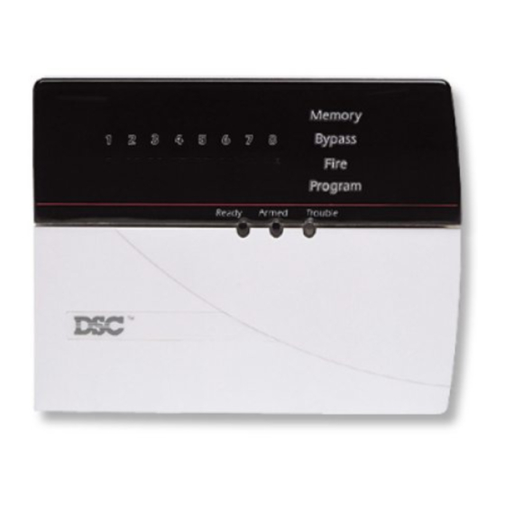
Module Operation and Programming
S
4.1 Module Zone Group Assignment
In order to use the zone expansion portion of the module, you must
select which system zones the expander will occupy.
Subsection [00] Module Zone Group Assignment will accept two
digits. The first corresponds to zone terminals 1-4 on the module
(Group A). The second digit corresponds to zone terminals 5-8
(Group B). Select which system zones these two groups will occupy
by entering the corresponding digit:
0 = Group Not Used
1 = Group Not Used
2 = Zones 9-12
3 = Zones 13-16
For example, to have Group A (Z1-Z4) occupy system zones 9-12,
and Group B (Z5-Z8) occupy zones 13-16, enter [23].
If using Downlook as well as zone expansion, consider the following:
Using zones connected to the PC5108L for Downlook triggering
means that images will be taken 25ms after an event has occurred.
See Section 4.2 "Downlook Operation (DLM-4L)" for more information.
Fire zones should not be used onPC5108L zones.
○ ○ ○ ○ ○ ○ ○ ○ ○ ○ ○ ○ ○ ○ ○ ○ ○ ○ ○ ○ ○ ○ ○ ○ ○ ○ ○ ○ ○ ○ ○ ○ ○ ○ ○
Module Zone Group Assignment ................................ Subsection [00]
○ ○ ○ ○ ○ ○ ○ ○ ○ ○ ○ ○ ○ ○ ○ ○ ○ ○ ○ ○ ○ ○ ○ ○ ○ ○ ○ ○ ○ ○ ○ ○ ○ ○ ○
4.2 Downlook Operation (DLM-4L)
When Downlook is initiated, the DLM-4L will store up to four images
from the programmed camera(s). Once the images are stored, the
Downlook module will seize the telephone line to transmit the images
to the central station. The images will be sent after the panel has
communicated the event.
When a Downlook module is connected to the PC5108L, the DLM-4L
Is Connected option must be enabled. In addition, the Local Mode
Enabled/Disabled option (PC5015 panel section [381] option [8])
should be OFF (default setting) if there is a DLM-4L present. If there is
no DLM-4L present on the system, this option should be ON.
Downlook can be initiated according to the following methods:
• Event-initiated Downlook
• Pre-trigger
• Remote trigger
All methods require similar programming. For each event/trigger, both
the Timing and Camera numbers for the transmissions must be
programmed.
The 2-digit Timing entry is the "dwell" time between pictures. That is,
when a camera is selected the picture is taken immediately and then
the PC5108L will freeze on that camera for the length of time specified
in the Timing entry. The value for this entry refers to 100's of ms. The 2-
digt Camera entry corresponds to the camera that will take the image.
E
C
T
4 = Zones 17-20
5 = Zones 21-24
6 = Zones 25-28
7 = Zones 29-32
I
O
5
N
4

