DSM SUM-40 Bedieningshandleiding - Pagina 5
Blader online of download pdf Bedieningshandleiding voor {categorie_naam} DSM SUM-40. DSM SUM-40 6 pagina's.
Motor speed (deg/sec)
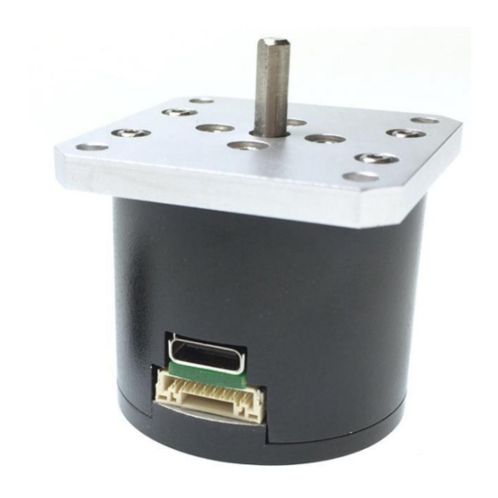
Connections and installation
The motor mounts via four 3.4mm clearance holes arranged in a 31 mm pattern. These clearance
holes can be used with either M3 or #4 screws. The output is a 4 mm diameter D-profile shaft
extending approximately 11.2 mm out of the face of the motor. DSM recommends the use of
flexible shaft couplers when installing the motor to avoid placing off-axis loads onto the motor
output shaft.
The motor has an internal bearing capable of supporting up to 20 N pulling away from the motor
or 10 N pushing into the motor. The bearing can also support a maximum of 20 N of radial load
applied to the tip of the output shaft. Motor performance may be degraded slightly when fully
loaded in this way. DSM recommends isolating the SUM-40 motor with external bearings and
couplers designed for correcting shaft misalignments.
The SUM-40 motor has two connections on it; one multi-function connector, and one USB type
C connector. The multi-function connector has one digital input, one digital output, RS-232
connections, a 12 V input, and a Ground connection. The USB type C connector is for
communication only. The SUM-40 must be powered by the multi-function connector, but
communication is possible either by the RS-232 pins on the multi-function connector or the USB
type C connector.
Max continuous runtime
100
400
800
1200
R. 171011
(minutes)
10
7
6
5
114 Southeast Parkway Ct.
Ste 160
Franklin, TN 37064
Tel: 615/595-6665
Fax: 615/595-6610
4