DigitaLinx DL-HD2100 Gebruikershandleiding - Pagina 6
Blader online of download pdf Gebruikershandleiding voor {categorie_naam} DigitaLinx DL-HD2100. DigitaLinx DL-HD2100 17 pagina's. Hdbaset extender set
Ook voor DigitaLinx DL-HD2100: Handleiding voor snelle installatie (8 pagina's), Handleiding voor snelle installatie (8 pagina's)

DL-HD2100 Owners Manual
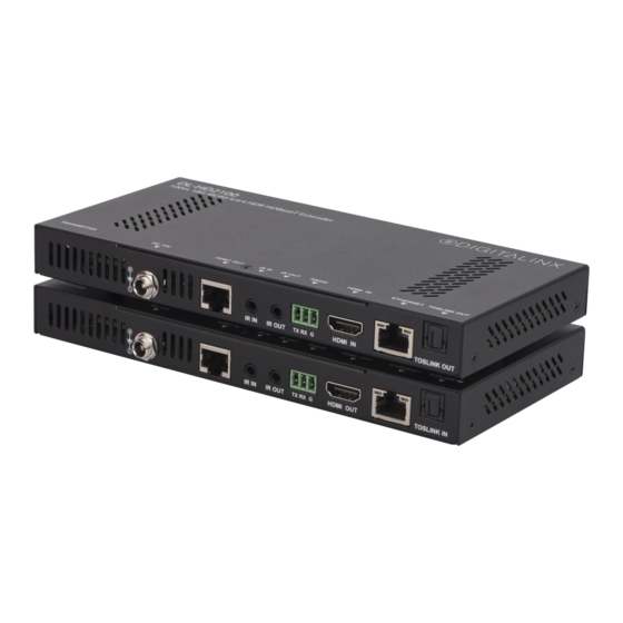
Receiver / Front and Back View
1. FRONT PANEL DIAGNOSTIC LEDs;
• POWER -Solid, the DL-HD2100 extender is receiving power from the power supply or from the
remote extender via Category 6 cabling.
• STATUS - Flashes once per second, the HDBaseT processor is running.
• HDCP - Solid, HDCP signal is present in the HDMI stream. Flashes quickly, non-encrypted HDCP signal
is present in the HDMI stream.
• LINK - Solid, the two DL-HD2100 components are communicating via Category cabling.
2. DC 12V
• Locking power port, connect DC12V power adapter to receiver (either power port on transmitter
and receiver can power entire set)
3. HDBT IN
• RJ45 HDBaseT connection. Connect Cat6 cable to transmitter
4. IR In / IR OUT
• 3.5mm IR input port for connection to IR receiver or IR system
• 3.5mm IR output port for connection to IR emitter
5. AUDIO CONTROL
• ARC - When ARC mode is selected, an HDMI cable from the HDMI OUT should connect to an ARC
compatible input on a display, digital audio will then de-embed from the TOSLINK OUT on the DL-
HD2100 transmitter
• TOSLINK - When TOSLINK mode is selected, a Toslink cable should be connected from the displays
digital audio output to the TOSLINK IN on the DL-HD2100 receiver, digital audio will then de-embed
from the TOSLINK OUT port of the DL-HD2100 transmitter
6. RS232
• 3 pin Phoenix connector port for connecting / passing RS232 control from transmitter location
7. HDMI In
• HDMI input port for connections to video sources
8. Ethernet
• RJ45 port for passing Ethernet from transmitter
9. TOSLINK IN
• Digital audio return channel input port for injecting digital audio signal from display (only in TOSLINK
mode)
6
1
2
3
4
5
6
7
8
9
