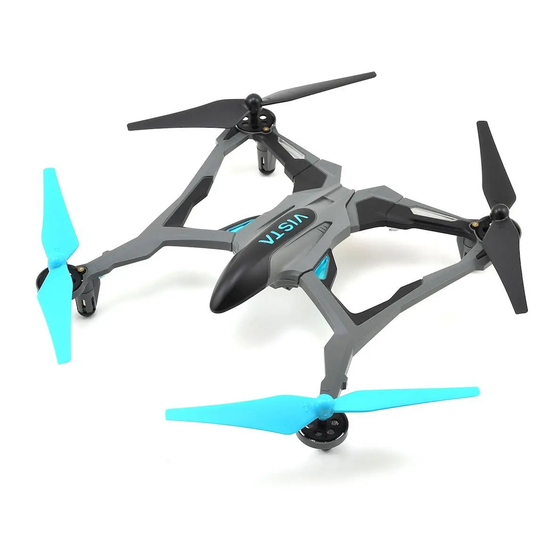
Dromida Vista UAV Podręcznik - Strona 2
Przeglądaj online lub pobierz pdf Podręcznik dla Quadcoptery Dromida Vista UAV. Dromida Vista UAV 6 stron.

DUAL RATES
The agility of the Vista can be changed by
pushing down on the right stick to select
low or high control rates.
The overall rate sensitivity can be adjusted by:
1. Holding down the right stick until the
controller beeps once.
2. Continue holding down the right stick and advance the left stick to the
desired setting.
3. Release the right stick and return the left stick to its lowest position.
The default setting is 50% (midstick) and low rates are 25% lower than
high rates.
FLIGHT MODES
The Vista has advanced stabilization which
automatically levels the quad when the right
stick is centered and limits how far the Vista
can tilt.
Press the Flight Mode button to toggle this
off or on.
Easy Mode – Control rates are at a low setting. This is the default mode for the
controller and should be used when indoors or if the pilot is just learning to fl y.
Normal Mode – The control
Mode
rates are high. This mode
Easy
should be selected when
Normal
flying outdoors or when
Advanced
more agility is desired.
Expert
Advanced Mode – Advanced stabilization is off and the control rates are
low. Your Vista will be more agile because there are no limits on how far it
can turn in any direction.
Expert Mode – Advanced stabilization is off and the control rates are high.
FLIPS
Your Vista can perform
a flip when the flip
button is pressed
followed by moving
the right stick in the
desired fl ip direction.
This stunt needs lots
of room and should
be done outside with
relatively calm winds.
LOW BATTERY INDICATORS
The fl ight time is about 10 minutes. When the battery voltage gets low, the
LEDs on the arms will fl ash slowly. The pilot should land as soon as possible
to avoid damaging the battery. The battery should always be charged before
the quadcopter is stored.
The controller will make a triple beep when the batteries need to be changed.
LED
Stab.
Sensitivity
Steady blue
ON
Low
Steady orange
ON
High
Flashing blue
OFF
Low
Flashing orange
OFF
High
SLT COMPATIBILITY
The Vista has a receiver that is compatible with other SLT transmitters
like the Tactic™ TTX650. A transmitter with an ANYLINK can also be used
provided it has helicopter programming, programmable mixing and at least
6 channels to control all the features of the Vista.
SETUP
Model Type: Heli with H1 (one servo) swashplate type
Servo Reversing: All Channels Normal (Tactic & Futaba)
Servo Travel: 125%/125% Ail. & Ele.
100%/100% Thr., Rud., and all switches
Throttle Curve: (0,25,50,75,100)
Gyro (Ch 5): 25%/75%/125% - These are
the sensitivity settings for the controls
Pitch Curve (Ch 6): Set all points to 100% on low switch position
- Advanced stabilization ON
Set all points to 0% on high switch position
- Advanced stabilization OFF
Dual Rates: 50%/125% Aileron & Elevator
Expo: -20/+100 Aileron & Elevator
Programmable Mixing: CH 1 to CH 6, Left = 125%, Right = -125%,
Use the dual rate switch (ON) as control
CH 2 to CH 6, Left = 125%, Right = -125%,
Use the dual rate switch (ON) as control
•
Use a momentary switch for the Dual Rate, Expo and Programmable
Mix settings.
•
The high rate settings should be assigned to the ON position and are
used for flipping.
QUADCOPTER SENSOR CALIBRATION
If the quadcopter is constantly drifting in the same direction or any time a
new fl ight control board has been installed, the sensors on the Vista should
be calibrated.
1. Center all the trim adjustments. To center the trim settings, hold down
one side of the trim button until you hear a long beep. If the controller
stops beeping, release the trim button and hold down the other side.
2. Place your Vista on a level
surface and link the quadcopter
with the controller.
3. Put the controller in Normal
Flight Mode (steady orange
Flight Mode LED).
4. Press and hold the right stick in
its lower right corner.
5. Move the left stick down and to the right. When the arm LEDs start to
fl ash, release both sticks. The LEDs will stop fl ashing when the calibration
is complete.
ROTOR BLADE REPLACEMENT
1. Remove screw that secures the rotor blade to the gear shaft.
2. Pull prop off the gear shaft.
3. Install new rotor blade and secure with screw.
