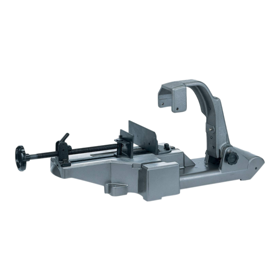
HIKOKI CB12-ST2 Instrukcje obsługi - Strona 5
Przeglądaj online lub pobierz pdf Instrukcje obsługi dla Piła HIKOKI CB12-ST2. HIKOKI CB12-ST2 16 stron. Band saw stand

<Adjustment of the perpendicularity between the top surface
of the base and the band saw blade>
(1) Apply the vise guide to vise (B), and lightly secure the
vise guide using vise (A). (Fig. 9)
Vise (A)
(2) Loosen the two band saw adjustment bolts using
the 8-mm hexagonal wrench supplied as a standard
accessory.
Hold the front handle and move the main unit up and
down to adjust its angle so that a uniform amount of
clearance is created between the side of the vise guide
and the band saw blade. (Fig. 10)
(3) Tighten the two band saw adjustment bolts to fi rmly
secure hinge (B).
NOTE
If a higher level of cutting precision is required, adjust the
vise position using a speed square.
Hinge (B)
Band saw
blade
Top surface
of the base
Side of the
vise guide
5. Setting the cutting load
In order to set the cutting load, lift and hold the main unit
at the upper limit position, then change the position of the
spring stopper. (Fig. 11)
When cutting thin wall steel pipes (with a wall thickness
of 2 mm or less), PVC, or plastic materials, set the cutting
load to "Light load" or "Lightest load".
NOTE
● When setting the cutting load, be sure to lift the main unit
to the upper limit position.
Vise guide
Vise (B)
Fig. 9
Band saw
adjustment bolts
Hinge (A)
Band
saw blade
Fig. 10
If the spring stopper is pressed in when the main unit is
in a low position, the force of the spring will be applied
in the opposite direction, preventing the main unit from
being able to be lifted to the upper limit position.
● Setting a lighter cutting load increases the length of time
required to cut workpieces, however, cutting precision
will be improved.
Pull out the spring stopper.
(Remove it from surface
Insert it into hole
.
Insert it into hole
.
Insert it into hole
.
Hole
Pin
Spring stopper
6. Securing workpieces
Vise (A) of the band saw stand can be moved faster
when the clutch is released, and can be used to press
a workpiece when the clutch is applied. You can carry
out your work effi ciently by appropriately moving the vise
faster and pressing it against workpieces.
(1) Place a workpiece on the top surface of the base, and
press it against vise (B).
(2) Release the clutch, and move vise (A) until it comes in
contact with the workpiece.
(3) Apply the clutch, and turn the knob clockwise to secure
the workpiece. (Fig. 12)
Workpiece
Clutch
Release
Tighten
Knob
NOTE
If the clutch cannot be released, turn the knob
counterclockwise a little.
5
English
"Heavy load"
.)
"Medium load"
"Light load"
"Lightest load"
Hole
Lighter
Hole
Heavier
Surface
A
Fig. 11
Vise (A)
Vise (B)
Apply
Fig. 12
