Empire VFP36PB2EF-3 Instrukcje instalacji i instrukcja obsługi - Strona 11
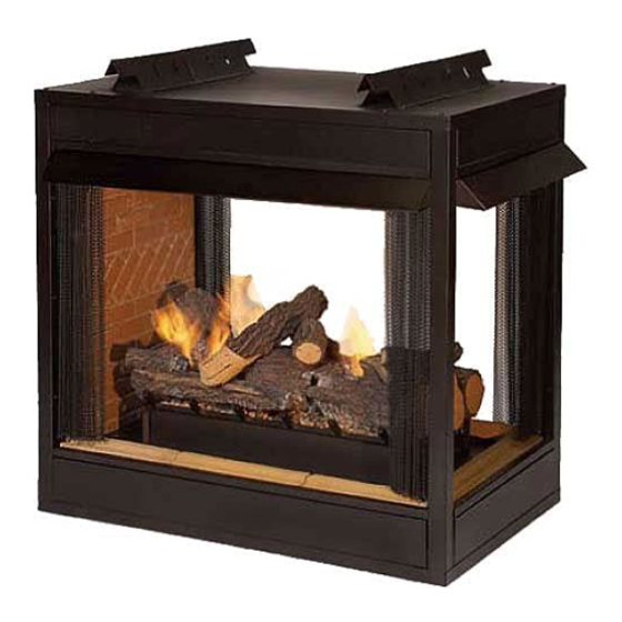
Przeglądaj online lub pobierz pdf Instrukcje instalacji i instrukcja obsługi dla Kominek wewnętrzny Empire VFP36PB2EF-3. Empire VFP36PB2EF-3 20 stron. Premium universal firebox for all vent-free log sets see-through firebox models peninsula firebox models
OPTIONAL SINGLE SPEED BLOWER INSTALLATION INSTRUCTIONS
Attention:
Install blower assembly before connecting
gas inlet supply line.
Wiring
The appliance, when installed, must be electrically grounded in
accordance with local codes or, in the absence of local codes,
with the National Electrical Code, ANSI/NFPA 70, if an external
electrical source is utilized. This appliance is equipped with
a three-prong [grounding] plug for your protection against
shock hazard and should be plugged directly into a properly
grounded three-prong receptacle. Do not cut or remove the
grounding prong from this plug. For an ungrounded receptacle,
an adapter, which has two prongs and a wire for grounding, can be
purchased, plugged into the ungrounded receptacle and its wire
connected to the receptacle mounting screw. With this wire com-
pleting the ground, the appliance cord plug can be plugged into the
adapter and be electrically grounded.
Caution: Label all wires prior to disconnection when servicing
controls. Wiring errors can cause improper and dangerous op-
eration. Verify proper operation after servicing.
Note: Junction box is to be located in the lower compartment of
the firebox and must be pre-wired at time of firebox instal-
lation for use with blower assembly. A standard ON/OFF
wall switch or optional SCV1 Variable Speed Control Kit
should be installed to activate power to the Junction Box
and provide power for the operation of the FBB5 Blower as-
sembly. It is recommended that installation of the wiring be
performed by a qualified electrician. See Figures 12 and
13.
1. If installed, turn OFF gas supply to firebox/gas log.
2. If applicable, turn OFF electric supply to firebox.
CAUTION: ALL WIRING SHOULD BE DONE BY A QUALI-
FIED ELECTRICIAN AND SHALL BE IN COMPLIANCE WITH
ALL LOCAL, CITY AND STATE BUILDING CODES. BEFORE
MAKING THE ELECTRICAL CONNECTION, MAKE SURE
THAT MAIN POWER SUPPLY IS DISCONNECTED. THE
APPLIANCE, WHEN INSTALLED, MUST BE ELECTRICAL-
LY GROUNDED IN ACCORDANCE WITH LOCAL CODES,
WITH THE NATIONAL ELECTRICAL CODE ANSI/NFPA 70
(LATEST EDITION).
To install the blower kit, access the junction box, or install a light
kit, remove the access cover plate and/or lower louvers or flush
panels as illustrated by figures 13 and 14.
A factory included junction box is located on the lower right side
of the firebox. Wiring must be fed through the 7/8" diameter hole
provided on the lower side of the firebox, and secured to the outer
wrap with the clamp provided. Leave approximately 6" of wire in
the junction box for connection.
Attach black wire to one side of the receptacle and white wire to
opposite side of receptacle. The ground wire should be attached
to the green (ground) screw. See Figure 12.
Install the receptacle into the junction box as illustrated.
Attach cover plate. Place Junction Box so that it is approximately 8
to 12" away from the outer wrap wall. Secure wiring at outer wrap
of fireplace with wire clamp provided.
27451-5-0614
Attention: If installed, do not damage gas inlet supply line when
blower assembly is inserted into firebox. In some cases, removal
of the gas inlet supply line may be necessary.
3. Determine which type of firebox you have prior to installation.
See Figures 13 and 14.
Figure 13 - Flush Or Louvered Models
BLOWER AND JUNCTION
BOX ACCESS COVER
PLATE
Figure 14 - Flush Face Models With Raised Hearth Exten-
Figure 12
sions
Page 11