Siemens SIPART PS2 Instrukcja instalacji - Strona 4

Przeglądaj online lub pobierz pdf Instrukcja instalacji dla Urządzenia przemysłowe Siemens SIPART PS2. Siemens SIPART PS2 11 stron. Mounting bracket kit
Również dla Siemens SIPART PS2: Instrukcja instalacji (4 strony), Instrukcja obsługi (28 strony), Instrukcja instalacji (4 strony), Instrukcja instalacji sprzętu (30 strony), Opis techniczny (26 strony), Kompaktowa instrukcja obsługi (35 strony), Instrukcja instalacji zestawu (9 strony)
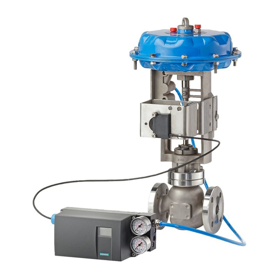
Siemens SIPART PS2 Instrukcja instalacji
15900-795
Assemble Retaining Clip to Feedback Lever
1. On the actuator nameplate, read the actuator model and valve travel for the actuator at hand. Find
that model and travel in Table 2 below. The retaining clip position is shown to the right of the valve
travel.
Actuator
Model
M-00
M-11
M-22
M-33
M-44-78
M-44-108
2. Orient the feedback lever (text side facing you) and retaining clip as shown in Figure 2. Align the
clip with the lever as shown in the selected row in Table 2. (Example: the clip location for a valve
travel of 3.07 is shown in Figures 2 and 3.)
3. Press the lever into the clip and lift the two hooked ends of the clip until they can be placed in two
notches in the lever and hook onto the lever. See Figure 3.
FIGURE 2 Pressing the Feedback Lever into the Retaining Clip
TABLE 2 Retaining Clip Location
Valve
Clip
Travel
Position
0.71"
1.10"
1
1.50"
2.28"
3.07"
2
4.25"
FIGURE 3 Placing the Retaining Clip on the Feedback Lever
Retaining Clip Location
4