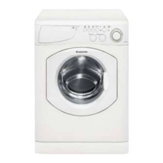
Ariston AWD 121 Instrukcja naprawy - Strona 16
Przeglądaj online lub pobierz pdf Instrukcja naprawy dla Spryskiwacz Ariston AWD 121. Ariston AWD 121 20 stron. Washer / washer-dryer combo
Również dla Ariston AWD 121: Instrukcje użytkownika (21 strony), Instrukcja instalacji i użytkowania (17 strony)

- 1. Table of Contents
- 2. Model & Serial Number Locations
- 3. Top Panel
- 4. Control Panel
- 5. Control Panel Components
- 6. Toe Kick & Drain Motor
- 7. Drum Boot
- 8. Door Switch
- 9. Water Valves
- 10. Heater Assembly (AWD 120 / 121 / 129 Only)
- 11. Pressure Switch
- 12. Rear Access Panel
- 13. Control Board
- 14. Main Motor
- 15. Fault Codes
- 16. Schematics
14. FAULT CODES (all Models except AW125)
A repair fault is signaled by the continuous rotating of the Program Knob and the flashing of the Door Locked LED. The Fault Code is
determined by counting the sequence of individual flashes of the LED (2 flashes = F2). The LED will flash the Fault Code sequence
and then delay for approximately eight (8) seconds, repeating the Fault Code sequence and eight second delay continually.
TECH NOTE: The unit can be turned off without harm and the Fault Code sequence will repeat when power is reapplied.
F1.
Triac Short
Replace Control Board.
F2.
Main Motor
Check Main Motor connections.
Replace Main Motor.
Or, replace Control Board.
F3.
NTC (Water Temp) Open / Short
Check wiring continuity to Control Board.
Replace NTC.
Or, replace Control Board.
F4.
Pressure Switch
Check wiring continuity to Control Board.
Replace Pressure Switch.
Or, replace Control Board.
F5.
Blocked Drain Motor or Pressure Switch shorted in Empty position
Check Drain Hose.
Check Drain Motor clean out for obstruction.
Check voltage at Drain Motor.
Check Pressure Switch wiring continuity.
Replace Drain Motor / Pressure Switch.
Or, replace Control Board.
F6.
Program Selector
Check wiring continuity to Control Board.
Replace Program Selector.
Or, replace Control Board.
F7.
Not Used
F8.
Pressure Switch Shorted in Full Position
Check Pressure Switch wiring continuity.
Or, replace Pressure Switch.
Or, replace Control Board.
REPAIR MANUAL
F9.
Control Board Error
Incorrect version of Control Board or EEPROM.
Change Control Board and EEPROM.
F10. Pressure Switch Shorted
Check wiring continuity to Control Board.
Replace Pressure Switch.
Or, replace Control Board.
F11. Drain Motor
Check wiring continuity to Control Board.
Check Drain Motor clean out for obstruction.
Voltage check at Drain Motor.
Check Pressure Switch.
Replace Drain Motor.
Or, replace Control Board.
F12. Not Used
F13 - F16 Apply Only AWD Models
F13. NTC (Dryer Temp) Open / Short
Check wiring continuity to Control Board.
Replace NTC.
Or, replace Control Board.
F14. Dryer Heating Element is Open
Check Dryer Heating Element continuity.
Check wiring from Element to Control Board.
Replace Heating Element.
Or, replace Control Board
F15. Dryer Heating Element Relay Shorted
Check Dryer Heating Element continuity.
Check wiring from Element to Control Board.
Replace Control Unit.
F16. Not Used
AW 120 / AW 122 / AW 125
AWD 120 / AWD 121 / AWD 129
Page: 13
