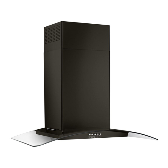
Whirlpool WVW51UC0FS Instrukcje instalacji oraz instrukcja obsługi i konserwacji - Strona 6
Przeglądaj online lub pobierz pdf Instrukcje instalacji oraz instrukcja obsługi i konserwacji dla Okap wentylacyjny Whirlpool WVW51UC0FS. Whirlpool WVW51UC0FS 9 stron. Wall‑mount canopy range hood
Również dla Whirlpool WVW51UC0FS: Instrukcje instalacji oraz instrukcja obsługi i konserwacji (28 strony), Instrukcje instalacji; Informacje dotyczące użytkowania i pielęgnacji (28 strony)

- 1. Installation Requirements
- 2. Location Requirements
- 3. Tools and Parts
- 4. Product Dimensions
- 5. Venting Requirements
- 6. Electrical Requirements
- 7. Installation Instructions
- 8. Prepare Location
- 9. Install Range Hood
- 10. Connect Vent System
- 11. Make Electrical Connection
- 12. Install Vent Covers
- 13. Complete Installation
- 14. Range Hood Use
- 15. Range Hood Controls
Install Range Hood
NOTE: Remove protective film from range hood and metal filters.
1. Using two or more people, hang range hood on two
mounting screws through the mounting slots on back of
hood.
B
A
A. Mounting screws
B. Mounting slots
C. Lower mounting screws
2. Remove the grease filter. See "Range Hood Care" section.
3. Level the range hood and tighten upper mounting screws.
4. Install (2) 5 x 45 mm lower mounting screws and tighten.
Use the optional wall anchors if needed.
Connect Vent System
1. Install transition on top of hood (if removed for shipping)
with (2) 3.5 x 9.5 mm sheet metal screws.
A
B
A. Vent transition
B. 3.5 x 9.5 mm screw
For vented installations only:
1. Fit vent system over the exhaust outlet.
2. Seal connection with clamps.
3. Check that back draft dampers work properly.
8
For non-vented (recirculating) installation only:
1. Assemble the air deflector with the duct cover bracket
using (4) 4.2 x 8 mm screws.
C
2. Measure from the bottom of the air deflector to the bottom
of the hood outlet.
3. Cut the duct to the measured size "X."
4. Remove the air deflector.
5. Slide the duct onto the bottom of the air deflector.
6. Place the assembled air deflector and duct over
the exhaust outlet from the hood.
7. Reassemble the air deflector to the duct cover
bracket with the four assembly screws.
8. Seal connections with vent clamps.
B
C
A. Assembly screws
B. Air deflector
C. Duct cover bracket
B
X
D
E
A. Air deflector
B. Vent clamp
C. X = length to cut vent duct
D. Vent duct
E. Exhaust outlet
A
A
C
