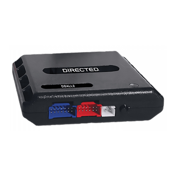
Directed Electronics Xpresskit DBALL Instrukcja instalacji - Strona 8
Przeglądaj online lub pobierz pdf Instrukcja instalacji dla Akcesoria samochodowe Directed Electronics Xpresskit DBALL. Directed Electronics Xpresskit DBALL 14 stron. Databus all combo bypass module
Również dla Directed Electronics Xpresskit DBALL: Instrukcja instalacji (14 strony)

Platform: DBALL
Firmware: GM5
Installation Type 5
OBDII (connector side view)
(+) 12v
(-) Ground
3: Green/White: (-) Door Status Output**
4: Red/Black: (-) Trunk Status Output**
5: Violet/White: (AC) Tach Output
*
Rear Hatch or Trunk Release Input
operation.
** If applicable - see the Function List.
Not required in D2D mode.
The Mobile Integration Systems
(+) Accessory Output
(+) Ignition 1 Output
(+) Ignition 2 Output
(+) Brake Input
Parking Lights
(AC) Tach Input
(-) Trunk Status Input**
(-) Door Status Input**
1
8
9
16
Diagnostic connector
2: Purple/Yellow: J1850
13: Red: (+) 12v
14: Black: (-) Ground
RF Loop Connector
Programming button
LED
: With vehicle with motorized rear hatch, this input will release the hatch. See programming options to change its
Vehicle CAN Bus Integration System
Ground
(-) Lock Output**
(-) Unlock Output**
(-) Rear Hatch or Trunk Release Output*
(+) Starter Output
(-) GWR (Status)
(+) Starter
10: Blue/White: (-) GWR (Status) Input
8: Violet: (+) Starter Input
Rear Hatch or Trunk Release Input*
3: Red/White: (-)
2: Blue: (-) Unlock Input**
1: Green: (-) Lock Input**
(+)12v
RX
(-) Ground
DBALL
TX
P#: XKD2D65
Rev.: 20101103
Hood Switch
(+) 12 V Input
© 2010 Directed Electronics. All rights reserved.
Page 8
