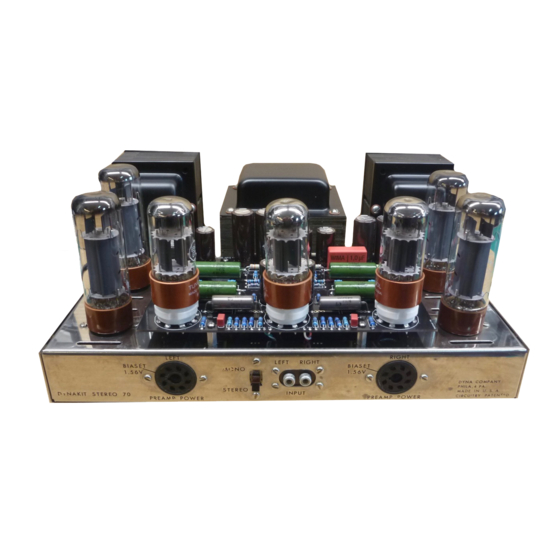
DYNACO 79-001 Manual de instruções de instalação - Página 2
Procurar online ou descarregar pdf Manual de instruções de instalação para Sistema estéreo DYNACO 79-001. DYNACO 79-001 6 páginas. Hifi hospital, original replacement pcb

The following steps require the use of a soldering iron. In the following steps, disconnect the
wires at the PCB end only, after unsoldering, bend wires away from PCB to avoid burning the
wire insulation with soldering iron. Avoid sharp bends to prevent breaking wire. (If wires appear to
be brittle, it is highly recommended that they be replaced with pre-tinned #20-#22AWG stranded
wire).
( ) Using a soldering iron, disconnect wire connected to eyelet #11 on PCB.
( ) Using a soldering iron, disconnect wire connected to eyelet #12 on PCB.
( ) Using a soldering iron, disconnect wire connected to eyelet #13 on PCB.
( ) Using a soldering iron, disconnect wire connected to eyelet #14 on PCB.
( ) Using a soldering iron, disconnect wire connected to eyelet #6 on PCB.
( ) Using a soldering iron, disconnect wire connected to eyelet #7 on PCB.
( ) Using a soldering iron, disconnect wire connected to eyelet #1 on PCB.
( ) Using a soldering iron, disconnect wire connected to eyelet #2 on PCB.
( ) Using a soldering iron, disconnect wire connected to eyelet #5 on PCB.
( ) Using a soldering iron, disconnect wire connected to eyelet #4 on PCB.
( ) Using a soldering iron, disconnect 10 ohm (brown, black, black) resistor
connected to eyelet #8 on PCB.
( ) Using a soldering iron, disconnect wire connected to eyelet #3 on PCB.
( ) Using a soldering iron, disconnect wire connected to eyelet #19 on PCB.
( ) Using a soldering iron, disconnect wire connected to eyelet #20 on PCB.
( ) Using a soldering iron, disconnect wire connected to eyelet #21 on PCB.
( ) Using a soldering iron, disconnect wire connected to eyelet #15 on PCB.
( ) Using a soldering iron, disconnect wire connected to eyelet #16 on PCB.
( ) Using a soldering iron, disconnect wire connected to eyelet #9 on PCB.
( ) Using a soldering iron, disconnect 10 ohm (brown, black, black) resistor
connected to eyelet #10 on PCB.
( ) Using a soldering iron, disconnect wire connected to eyelet #17 on PCB.
( ) Using a soldering iron, disconnect wire connected to eyelet #22 on PCB.
( ) Using a soldering iron, disconnect wire connected to eyelet #23 on PCB.
( ) Using a soldering iron, disconnect wire connected to eyelet #18 on PCB.
( ) Using a pair of wire cutters/ strippers, disconnect two (2) remaining wires connected to PCB,
cut wires as close to the PCB as possible (these wires will be reconnected to the new PCB).
2
