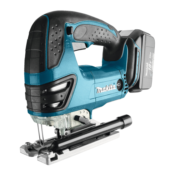
Makita BJV180 Informações técnicas - Página 7
Procurar online ou descarregar pdf Informações técnicas para Ferramenta eléctrica Makita BJV180. Makita BJV180 13 páginas. Cordless jig saw
Também para Makita BJV180: Repartição das peças (3 páginas), Ficha de especificações (2 páginas), Manual de instruções (13 páginas), Manual de instruções (13 páginas), Manual de instruções (13 páginas), Manual de instruções (18 páginas)

R
epair
[3] DISASSEMBLY/ASSEMBLY
[3] -2. Gear Housing Cover Section (cont.)
ASSEMBLING
9) Lubricate the parts assembled to Gear housing cover
complete with reference to "Lubrication" in page 2.
10) While fitting Needle bearing 407 on Crank complete
in the groove portion of Slider, assemble Gear housing
cover section to Gear housing complete as illustrated
in Fig. 19.
Note: Do not forget to put Packing between Gear
housing cover complete and Gear housing.
(Fig. 7 in page 4)
[3] -3. Blade Holder
DISASSEMBLING
1) Take out Rod from Gear housing cover section. (Figs. 6, 7 in page 4; Figs. 8, 9, 10 in page 5)
2) Remove Dust cover and Retaining ring R-18 as illustrated in Fig. 20.
3) Blade holder and Torsion spring 15 can now be separated from Rod. (Fig. 21)
Note: Be careful not to lose Push pin.
Fig. 20
Dust cover
Rod
Retaining ring R-18
Blade holder
ASSEMBLING
1) Apply Makita grease FA No.2 to Push pin. Put Push pin in the hole of Rod, and assemble Torsion spring 15 to Rod
as illustrated in Fig. 22.
2) Put Rod on Blade holder while aligning Push pin with the mark on Blade holder. (Fig. 23)
3) Turn the outward bent end of Torsion spring in the direction of the arrow, and put in the protruding space of Blade
holder. (Fig. 24)
3) Secure Blade holder with Retaining ring R-18 using 1R311, then assemble Dust cover to Rod. (Fig. 20)
Fig. 22
Rod
Push pin
outward bent end
Insert the inward bent end of
Torsion spring 15 into the hole of Rod.
Fig. 23
Push pin
mark
inward bent end
Torsion spring 15
Blade holder
Fig. 19
groove portion
of Slider
Gear housing
cover complete
Gear housing cover section
Fig. 21
1R311
Push pin
Fig. 24
outward bent end
of Torsion spring 15
P 7/13
Needle bearing 407
Crank complete
Gear housing
complete
Torsion spring 15
Blade holder
protruding space
