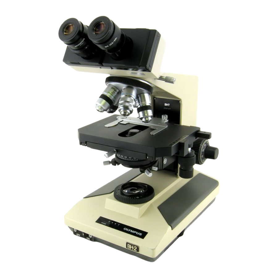
Olympus BH2 Series Desmontagem, limpeza e remontagem - Página 5
Procurar online ou descarregar pdf Desmontagem, limpeza e remontagem para Microscópio Olympus BH2 Series. Olympus BH2 Series 45 páginas. Phase contrast
Também para Olympus BH2 Series: Manual de resolução de problemas e ajuste (46 páginas), Desmontagem, limpeza e remontagem completas (23 páginas), Desmontagem, limpeza e remontagem completas (40 páginas), Manual (6 páginas), Manual de instalação (9 páginas)

Figure 84 - Carefully lift and remove the diaphragm rotor ........................................................................................... 23
Figure 85 - Diaphragm leaves in the metal stator ......................................................................................................... 24
Figure 86 - Carefully remove the diaphragm leaves ..................................................................................................... 24
Figure 87 - Thoroughly clean the diaphragm stator ...................................................................................................... 24
Figure 88 - Thoroughly clean the diaphragm leaves ..................................................................................................... 24
Figure 89 - Thoroughly clean the field diaphragm rotor ............................................................................................... 24
Figure 90 - Features of the field diaphragm leaves ....................................................................................................... 25
Figure 91 - Mark the location of the pivot holes in stator ............................................................................................ 25
Figure 92 - Reinstall first diaphragm leaf into the stator .............................................................................................. 25
Figure 93 - First leaf installed in field diaphragm stator ............................................................................................... 25
Figure 94 - Install the second diaphragm leaf ............................................................................................................... 25
Figure 95 - Continue installing the field diaphragm leaves ........................................................................................... 25
Figure 96 - First seven field diaphragm leaves installed ............................................................................................... 26
Figure 97 - Use index finger to hold the leaves down ................................................................................................... 26
Figure 98 - Lift free end of leaves to slip the next one in .............................................................................................. 26
Figure 99 - Slip seventh leaf under the lifted leaves ..................................................................................................... 26
Figure 100 - Position leaves against the stator side wall .............................................................................................. 26
Figure 101 - Proper orientation of field diaphragm rotor ............................................................................................. 27
Figure 102 - Carefully reinstall the field diaphragm rotor ............................................................................................ 27
Figure 103 - Verify smooth operation of field diaphragm ............................................................................................ 27
Figure 104 - Close field diaphragm to a pinhole aperture ............................................................................................ 27
Figure 105 - Orientation of the screw holes in the rotor .............................................................................................. 27
Figure 106 - Reinstall brass retaining plate onto stator ................................................................................................ 28
Figure 107 - Reinstall screws to secure the retaining plate .......................................................................................... 28
Figure 108 - Reinstall plastic gear collar onto the rotor ................................................................................................ 28
Figure 109 - Secure the gear collar with two screws .................................................................................................... 28
Figure 110 - Reinstall the slotted stop pin into the rotor ............................................................................................. 28
Figure 111 - Ready to be installed into scope (old style) .............................................................................................. 28
Figure 112 - Remove screws securing brass plate to stator .......................................................................................... 29
Figure 113 - Align plastic tab with notch in brass plate ................................................................................................ 29
Figure 114 - Lift and remove the brass retaining plate ................................................................................................. 29
Figure 115 - Lift and remove the plastic rotor from stator ........................................................................................... 29
Figure 116 - Thoroughly clean the plastic rotor ............................................................................................................ 29
Figure 117 - Carefully place the plastic rotor into position ........................................................................................... 30
Figure 118 - Reinstall brass retaining plate onto stator ................................................................................................ 30
Figure 119 - Reinstall screws to secure the retaining plate .......................................................................................... 30
Figure 120 - Plastic stop tab hits tab on retaining plate ............................................................................................... 30
Figure 121 - Ready to be installed into scope (new style) ............................................................................................ 30
Figure 122 - Place field diaphragm assembly into position .......................................................................................... 31
Figure 123 - Secure field diaphragm assembly to base ................................................................................................. 31
Figure 124 - Light Inlet Assembly for the BHT/BHTU .................................................................................................... 31
Figure 125 - Remove setscrews securing barrel to base ............................................................................................... 31
Figure 126 - Remove the Light Inlet Assembly from base ............................................................................................. 31
Figure 127 - Carefully loosen the upper retaining ring ................................................................................................. 32
Figure 128 - Remove the upper retaining ring .............................................................................................................. 32
Figure 129 - Carefully lift and remove adiabatic glass disk ........................................................................................... 32
Figure 130 - Remove the upper spacer tube ................................................................................................................. 32
Figure 131 - Carefully lift and remove frosted glass disk .............................................................................................. 32
Figure 132 - Remove the lower spacer tube ................................................................................................................. 32
Figure 133 - Remove the glass collector lens ................................................................................................................ 33
Figure 134 - The lower retaining ring in the barrel ....................................................................................................... 33
Figure 135 - Loosen the lower retaining ring ................................................................................................................ 33
Figure 136 - Remove the lower retaining ring .............................................................................................................. 33
Teardown, Cleaning, and Reassembly of the Miscellaneous Parts of the Olympus BH-2 Microscope Frames
Revision 1
Page 5 of 45
