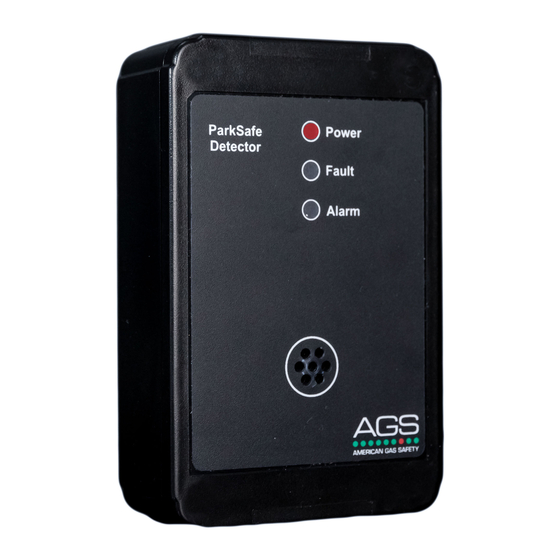
AGS Parksafe Control Panel Руководство по установке и эксплуатации - Страница 6
Просмотреть онлайн или скачать pdf Руководство по установке и эксплуатации для Контроллер AGS Parksafe Control Panel. AGS Parksafe Control Panel 16 страниц. Ventilation control panel
Также для AGS Parksafe Control Panel: Руководство по установке и эксплуатации (16 страниц), Установка, эксплуатация и обслуживание (16 страниц), Руководство по установке, эксплуатации и техническому обслуживанию (20 страниц)

Installation & Operation Manual
Board Connections Overview
1. POWER/ LINE IN 110-120Vac mains power should be supplied to the [POWER/LINE IN] connector
using a 3 core cable and fused at 3A. When mains power is supplied to the panel - a red LED
will illuminate located on the front cover.
2. OUTPUT 1 RELAY This relay output switches when any external gas detectors reach 'pre-alarm'
status and the [0-10V OUTPUT] will send 5V to ventilation systems.
OUTPUT 2 RELAY This relay output switches when any external gas detectors reach 'alarm delay'
status and the [0-10V OUTPUT] will send 10V to ventilation systems.
ALARM RELAY This relay output switches when any external gas detectors reach 'alarm delay'
status for longer than the selectable 1-5 minutes time following the [OUTPUT 2] relay.
DAMPER RELAY This relay output can switch together with either OUTPUT 1, OUTPUT 2 or ALARM
relays - selectable in the settings menu.
3. DETECTOR CHAIN 12-24Vdc power and Modbus communication data is wired to Parksafe gas
detectors [DETECTOR CHAIN] - [+ / - / D+ / D-].
Up to 16 detectors can be connected, chained in parallel up to approx. 500 yards from the
panel depending on chain configuration, wire type for power and condition.
Connect detectors in a parallel (daisy chain) method. Any other way may cause
communication issues or damage to the overall system.
For MODBUS communications, a shielded and twisted pair cable is used. The shielding can be
of 2 types: braided [mesh of thin conducting wires] or foil (consisting of a thin sheet of metal
covering the twisted wires).
If you are encountering noise or irregular problems with a Modbus link, the problem is likely
related to grounding, incorrect shielding or wiring mains power next to Modbus wiring.
For more information refer to your Parksafe detector manual.
4. SOUNDER/ STROBE This relay output (24VDC) is for an external sounder alarms/ strobe lighting to
activate on alarm.
5. 24VDC This is a permanent 24Vdc power output for external auxiliary devices.
Max output: 200mA.
6. 0-10V OUTPUT This output can drive ventilation systems. Under normal operating conditions, this
output can send either 0 or 2V – selectable in the settings menu. The [0-10V OUTPUT] will send 5V
when [OUTPUT 1] relay is activated and 10V when [OUTPUT 2] relay is activated.
AGS Parksafe Panel - IOM Iss: 6 10-20
Parksafe
6
