bolid S2000-KPB Kullanım Kılavuzu - Sayfa 5
Kontrol Ünitesi bolid S2000-KPB için çevrimiçi göz atın veya pdf Kullanım Kılavuzu indirin. bolid S2000-KPB 14 sayfaları. Executive module
Ayrıca bolid S2000-KPB için: Kullanım Kılavuzu (17 sayfalar)
Note:
– In case of a short output failure in the moment of switching on the output, the
Output control commands with the programs #5, #6, #7, and #8 (Switch OVER) can include
detailed data defining a rate and pulse ration of switching the outputs. If these data are missed in a
command, the output will be switched over with 1 Hz frequency and pulse ratio of 2.
Output control commands with the programs #3, #4, #7, #8 («Switch for a Given Time») and
11 («Discharge») contain the Control Time parameter. The Control Time can have a value from 0 to
8192 s (2 hours 16 minutes and 32 s) in the increments of 0.125 s.
For the programs #3, #4, #7, #8 a program is executed for a given time and then the output is
switched off (the programs #3 and #7) or switched on (the programs #4 and #8). If Control Time is
missed or equal to zero then the output will not be activated.
In case of an output control command with the program #11 the module generates a discharge
pulse (the output is switched on for a given time and then the output is switched off). If Control Time
is missed or equal to zero then the output is activated for the time given by the module's Activation
Time parameter.
The module provides monitoring of executive outputs and monitored circuits connected to them.
The monitored states of a circuit are defined by its type specified in the configuration parameters in
accordance with Table 3.
Circuit Type
1
2
3
4
States of monitored circuits are defined by the voltage value on the negative output terminal
relative to the «0 V» terminal:
–
«Norm»: 0.5 V to 2.5 V in case of disabled output and 0.1 V to 0.9 V when the output is active;
–
«Open Failure»: more than 2.5 V for the disabled output and less than 0.1 V when the output is
active;
–
«Short Failure»: less than 0.5 V for the disabled output and more than 1 V when the output is
active.
When a short or open failure of a monitored circuit has been detected, the module transmits a
relative message over the RS-485 interface. When the monitored circuit has returned from the
monitored state to the Norm state, the module sends the relevant recovery message over the RS-485
interface.
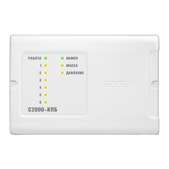
States of the control outputs and the monitored circuits connected to them in Quiescent Mode are
indicated by "1" to 6" LEDs in accordance with Table 4.
Circuit's
Output's
Condition
Condition
Norm
output is not switched on. If the module is connected to the internal interface
RS-485-2 of an S2000-ASPT device, the S2000-KPB module operates to
expand discharge circuits. Centralized control of individual outputs of the
module by the S2000M console in such case is disabled.
The circuit is monitored for open failure
The circuit is monitored for short failure
The circuit is monitored both for open and short failures
On
Off
Monitored Conditions
No circuit condition is monitored
Indicator Behavior
Lit steady in green
Table 3. Types of Monitored Circuits
Table 4. Indication of States of Outputs
Off
5