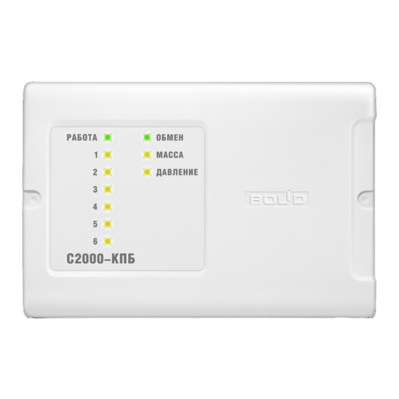
bolid S2000-KPB Kullanım Kılavuzu - Sayfa 7
Kontrol Ünitesi bolid S2000-KPB için çevrimiçi göz atın veya pdf Kullanım Kılavuzu indirin. bolid S2000-KPB 14 sayfaları. Executive module
Ayrıca bolid S2000-KPB için: Kullanım Kılavuzu (17 sayfalar)

Parameter
On/Off Events
Monitor For
Discharge Delay
Start Interval
Discharge Time
Both Power Inputs
Monitoring
If Both Power Inputs Monitoring is switched on, the module generates messages POWER FAILED
and POWER RESTORED individually for each power input. In such case a Power Failed message for
all the module is generated in state of the first power failure of any input while a Power Restored
message for the module as a whole is generated when the power has been restored for both the inputs.
To change configuration parameters of the module, an IBM compatible PC and one of the Bolid
manufactured interface converters (such as PI-GR, S2000-PI, S2000-USB etc.) are to be used. The
configuration parameters are changed by means of UProg Configuration Tool of version 4.1.0.3 or
higher.
The last version of UProg Configuration Tool along with some additional information about
operating the module can be found in the Internet at the address of www.bolid.com.
2.2 Power Failed Mode
The module enters the Power Failed mode on power voltage's dropping below 10 V at any input (if
Both Power Inputs Monitoring is set on) or at both inputs (if Both Power Inputs Monitoring is set off).
In such case the module transmits a Power Failed message over the RS-485 interface. READY LED
starts switching on for 0.25 s each 2 seconds.
When the power voltage has been restored for both inputs (if Both Power Inputs Monitoring is set
on) or for any input (if Both Power Inputs Monitoring is set off) up to 11 V and higher, the module
transmits a Power Restored message over the interface. In this case READY LED is lit steady.
The Power Failed mode of the module is indicated by its READY LED as shown in Table 7.
1. Power voltage at any input has dropped below the normal
value (Both Power Inputs Monitoring is set on)
2. Power voltage at both inputs has dropped below the normal
value (Both Power Inputs Monitoring is set off)
Description
Generating events on
changing states of the output
relay
The value defining monitored
conditions of the monitored
circuit
The duration of the discharge
delay for Program #11 (if
missed in the command)
The time between issuing
start pulses to adjacent
outputs for Program #11
The time of activation of the
output for Program #11
Generating events for each
power input individually
Operation Mode
Value
ON / OFF
1...4
Other
0...255 s
0...255 s
0...255 s
ON / OFF
Table 7. Indication of the Power Failed Mode
Default Value
ON
4
(Monitor for Open and Short
Failure)
2 s
7 s
5 s
ON
Indicator Behavior
Switches on
for 0.25 s each 2 seconds
7
