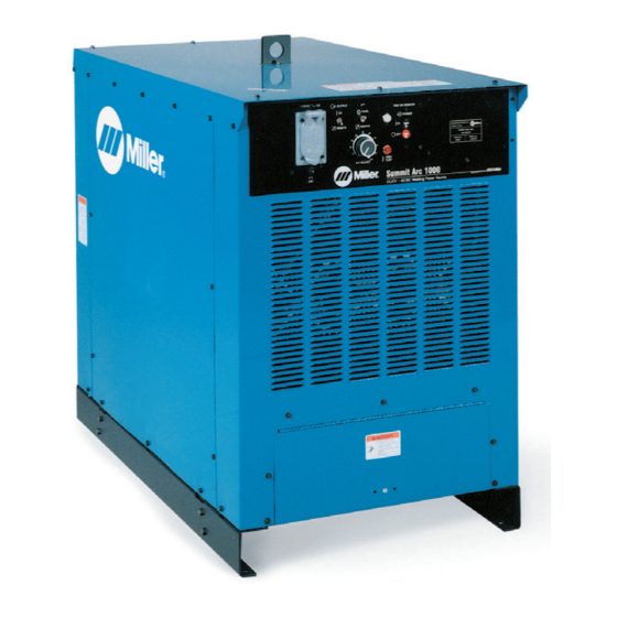
Miller Subarc DC 1000 Kullanıcı El Kitabı - Sayfa 28
Taşınabilir Jeneratör Miller Subarc DC 1000 için çevrimiçi göz atın veya pdf Kullanıcı El Kitabı indirin. Miller Subarc DC 1000 48 sayfaları.

3-6. Synchronizing Outputs For Parallel AC Arcs
Y All synchronized units must be set up for ac output ac-
cording to Section 2-9. Do not mix dc and ac output units.
.
Use two-conductor (12 to 20 gauge), with uninsulated ground,
shielded cable to make TE4 connections. Connect ground to
terminal C on TE4.
2
Connections from first to second
welding power source:
terminal A to terminal E,
terminal B to terminal B,
terminal C to terminal C
A
B
C
D
E
TE4 on first
welding power
source
Tools
Needed:
OM-2221 Page 24
Y If there are any questions regarding this procedure,
contact the factory before connecting units.
3/8 in
(10 mm)
Connections from second to third
A
B
C
D
E
TE4 on second
welding power
source
Terminal Strip TE4 Connections For Operating Multiple AC Units In Parallel
1
A
A
B
B
C
C
D
D
E
E
1
3
welding power source:
terminal A to terminal E,
terminal B to terminal B,
terminal C to terminal C
A
B
C
D
E
TE4 on third
welding power
source
Y Turn Off welding power
source and disconnect input
power before opening ac-
cess door.
1
Terminal Strip TE4
This procedure allows the ac out-
puts of two or more units to be syn-
chronized
so
the
match. To synchronize outputs,
make connections between termi-
nal strip TE4 on each ac output unit
as shown in illustration.
.
Do not disturb factory connec-
tions to terminal strip TE4.
Y Ensure that primary input
power conductors are con-
nected to each unit in the
same sequence (L1 to L1, L2
to L2, and L3 to L3). See Sec-
tion 2-15 for information on
connecting input power. See
Section 2-16 for information
on testing for proper primary
phase sequence.
Y Always test for correct phas-
ing before paralleling ac out-
puts according to Section
3-9.
2
Lead Being Connected To
TE4
3
Securing Screw
Strip 3/8 in (10 mm) insulation off
end of lead, insert end into proper
location on TE4, and tighten appli-
cable securing screw.
Close and secure access door.
.
Make certain control board
PC1 is set for synchronized
parallel ac arcs (see Section
3-8).
Connections from third to fourth
welding power source:
terminal A to terminal E,
terminal B to terminal B,
terminal C to terminal C
Y When using multiple arcs in
parallel, be sure to follow
unit setup instructions care-
fully. Severe damage to units
may occur if units are not
correctly connected for par-
allel operation.
Repeat same connection se-
quence on following
welding power sources
waveforms
ST-801 882-A
