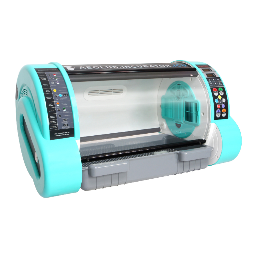
aeolus UC-1801 Hızlı Başlangıç Kılavuzu - Sayfa 10
Aksesuarlar aeolus UC-1801 için çevrimiçi göz atın veya pdf Hızlı Başlangıç Kılavuzu indirin. aeolus UC-1801 12 sayfaları. Professional vet equipments supplier

Water Level
Sensor
Figure 8.3.3-c
3. Complete Cleaning and Maintenance: remove and clean parts and assemblies periodically. Desired
results are achieved only by cleaning after removal.
Steps for Disassembling Components:
Remove four screws from the master control rack on the right to take down the right master control rack,
(remove the left master control rack in the same way). See figure. 8.3.1.
Remove power connection plugs on power cords on one side of the master control rack one by one. Note
that plugs have different colors for each electrical component.
Warning: do not remove control racks or electrical components from control racks immediately after shut
down; give it some time to cool down. The heaters in control racks reach high temperature. Remove control
racks or contact heaters after a 30 minutes respite after shutdown.
Remove four screws
Take down the rack
Figure 8.3.1-a
Remove four screws in the fan box and take out the whole heater. Clean the fan. Try not to remove heat sinks
from the fan, especially PTC heater bands that cannot be removed from heat sinks. See figure. 8.3.2.
Remove and clean filters behind the square plastic section inside the chamber.
Remove four
screws of fan
PTC Heater
Fan
Figure 8.3.2-a
Figure 8.3.3-d
Temperature
Humidity sensor
Humidifier
Right fan
Anion
Carbon filters
PTC Heater
Figure 8.3.1-b
PTC Heater
Fan
Figure 8.3.2-b
16
4. Cleaning
The ICU must be empty at the time of cleaning. Cleaning is feasible only after removal.
5. Maintenance
It is suggested to maintain the machine every two months during normal operation, which shall be carried
out in accordance with removal, installation and maintenance procedures above.
Trouble-shooting
Phenomenon
Cause analysis
After the power switch is pressed,
1.Bad power connection and
there is no reaction or the power
plug connection
indicator lamp is still off
2.Damaged switch
1.Too big atmizing particles of
solution causes little atomizing
volume
Little atomizing volume form the
2.Solution contains syrup or
medical atomizer
colloform
3.Tablets are used for
dissolution
4.Oily impurities on the surface
of solution
1.Water shortage of the
water tank of the atomizer
2.Damaged ultrasnic chip of
No atomizing form the
the atomizer
atomizer
3.Water scale in the tank of
the atomizer
Atomizing time and volume
Remaining solution not atomized
depend on concentration of
in the cup after atomization of the
atomizing liquid
medical atomizer
Solution
1. Check power connection
2.Replace the power switch
1.Too big particles are not
suitable for operation of this
atomizer
2.When solution contains syrup
or colloform,it requires with dry
filter paper
3.When tablets are used for
dissolution,dissolve sediments
to remove impurites first
4.Remove oily impurities on the
surface of solution with clean
tissue firstivvv
1.Add water into the water tank
until it is at the same level of
the cup bottom
2.Replace the ultrasonic chip
3.Gently scrub the inside of
the tank with lint
Repeat the atomization
operation procedure if not
completely atomized once
17
