Alemite 8568-MA Servis Kılavuzu - Sayfa 6
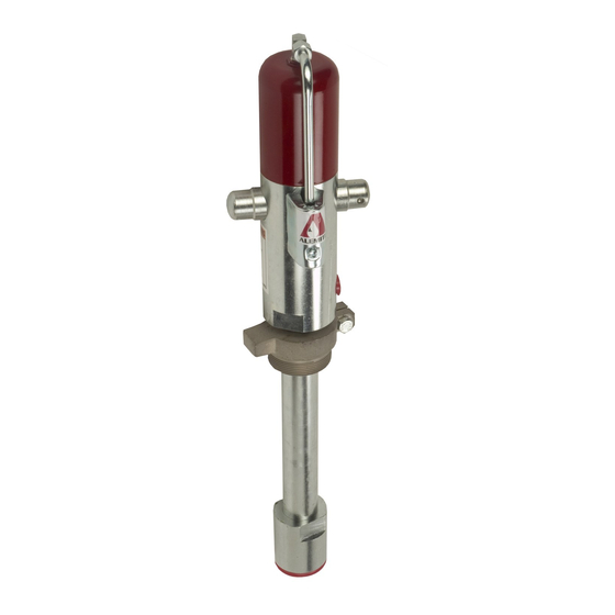
Su Pompası Alemite 8568-MA için çevrimiçi göz atın veya pdf Servis Kılavuzu indirin. Alemite 8568-MA 10 sayfaları. Medium-pressure stub pump

SER 8568-A4
Pump Tube
6. Place the pump tube in a vise at the Valve Seat with the
Coupling Rod facing upward.
7. Remove Tube Adapter (5) from Tube and Guide
assembly (17).
8. Grasp the Coupling Rod and pull the piston assembly
from the Tube and Guide assembly.
NOTE: Use care not to lose Spring (19) and
Valve Disk (20) during the next disassembly
procedure.
9. Remove the Tube and Guide assembly from the Valve
Seat.
• Use the Bung Adapter as a lever.
10. Remove the Spring and the Valve Disk.
CAUTION
Support Rod Coupling (8) and Piston Adapter (9)
during Roll Pin removal. Damage to components
can occur.
11. Remove Roll Pin (8) that secures Piston Adapter (7) to
Coupling Rod (6).
• Use a punch and a small hammer.
12. Unscrew the Coupling Rod from the Piston Adapter.
NOTE: Use care not to lose Spring (11) and
Ball (1 2) dur ing the next d isassem bly
procedure.
13. Unscrew the Piston Adapter from the Piston assembly.
14. Remove the Spring and the Ball from the assembly.
IMPORTANT: Should the pump contain the
obsolete piston (see Figure 5), discard the
assembly and use the conversion kit for
replacement.
15. Remove Wear Rings (13), O-Ring (15) and Back-Up
Washer (16) from Piston (14).
16. Remove O-Ring (6) from the Valve Seat.
17. Remove O-Ring (4) and O-Ring (6) from the Tube
Adapter.
18. Remove the Bung Adapter from the Tube and Guide
assembly as required.
Revision (7-05)
Clean and Inspect
NOTE: Use the appropriate repair kit for
replacement parts. Make sure all the compo-
nents are included in the kit and in good
condition before discarding used parts.
1. Clean all metal parts in cleaning solvent. The solvent
should be environmentally safe.
2. Inspect all parts for wear and/or damage.
• Replace as necessary.
3. Inspect Piston (14) closely. Use a magnifying glass to
detect any wire draw marks.
• Replace as necessary.
4. Closely inspect the mating surfaces of all components
for any imperfections. Ensure a smooth and clean
contact is obtained when assembled.
EXAMPLE: Place Ball (12) into Piston
(14). Fill the Piston with solvent. Make sure
no leakage occurs.
5. Measure the depth of the Guide within Tube and
Guide Assembly (17). The distance must be 1-3/16 "
(30 mm). Replace as necessary.
• See Figure 5.
Assembly
N O T E : P r i o r t o a s s e m b l y, c e r t a i n
components require lubrication in clean oil.
Refer to Table 4 for details.
Pump Tube
1. Place Ball (12) into Piston (14).
2. Screw Piston Adapter (9) into the Piston.
• Tighten securely.
Item No.
on Figure 2
4
O-Ring, 1-1/8 " ID x 1-1/4 " OD
6
O-Ring, 1 " ID x 1-1/4 " OD
13
Ring, Wear, (Glass-Filled Nylon)
15
O-Ring, 15/16 " ID x 1-3/16 " OD
16
Washer, Back-Up (Nylon)
Table 4 Lubricated Components
6
Medium-Pressure Stub Pump
Description
Alemite, LLC
