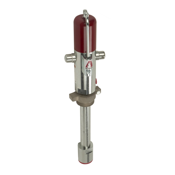
Alemite 8568-MA Servis Kılavuzu - Sayfa 8
Su Pompası Alemite 8568-MA için çevrimiçi göz atın veya pdf Servis Kılavuzu indirin. Alemite 8568-MA 10 sayfaları. Medium-pressure stub pump

SER 8568-A4
15. Position the top of the Piston Adapter level with the
bottom thread in the tube.
16. Screw Tube Adapter (5) [holes upward] into the Tube
and Guide assembly and tighten securely.
• Use care when passing over the O-Ring.
Connect Pump Tube to Air Motor
17. Place Air Motor assembly (1) in a vise with the piston
rod facing upward.
18. Thread Coupling Rod (8) onto the piston rod until the
pin holes are in alignment.
19. Lubricate Pin (7) with grease to prevent loss during the
installation process.
20. Install the Pin that secures the piston rod to the
Coupling Rod.
21. Thread the Tube Adapter into the air motor and tighten
securely.
• Use care when passing over the O-Ring.
Operation
Bench Test and Prime
NOTE: Perform the following procedures at
a pressure not to exceed 40 psi (2.8 bar).
1. Make sure air pressure at the regulator reads zero.
2. Connect a product hose to the pump's material outlet.
3. Place the hose into an appropriate collection container.
4. Install Air Connector (2) to the inlet of the Air Motor.
5. Connect an air line to Air Coupler (3).
6. Connect the Air Coupler to the Connector.
7. Slowly supply air pressure to the pump's motor.
• The pump assembly should cycle.
If the pump assembly does not cycle, refer to the
Troubleshooting Chart for details.
Priming
With air pressure at zero:
8. Place the pump in the product to be dispensed.
9. Slowly supply air pressure to the pump's motor.
10. Allow the pump to cycle slowly until the system and
product is free of air.
Revision (7-05)
If the pump assembly does not prime, refer to the
Troubleshooting Chart for details.
11.Check the motor for air leakage.
If the motor leaks, refer to the Air Motor Service
Guide for details.
Stall Test
WARNING
Should leakage occur anywhere within the
system, disconnect air to the motor. Personal
injury can occur.
With air pressure at zero:
12. Attach a control valve to the outlet hose of the pump.
13. Set the air pressure to 100 psi (6.9 bar).
14. Operate the control valve into a container.
15. Allow the pump to cycle until the system and product
is once again free of air.
16. Shut off the control valve.
• The pump should not cycle.
If the pump cycles once or continuously, refer to the
Troubleshooting Chart for details.
Installation
Screw the pump assembly into its system at Valve
Seat (21) or Bung Adapter (18).
• Tighten securely.
Additional items that should be incorporated into the
air piping system are illustrated in Table 5.
Part Number
338860
Moisture Separator/Regulator & Gauge Combination
5604-2
Moisture Separator
7604-B
Regulator and Gauge
5904-2
Lubricator *
Table 5 Air Line Components
* Although the air motor is lubricated at the factory,
the life of the motor can be extended with the use of a
lubricator.
8
Medium-Pressure Stub Pump
Description
Alemite, LLC
