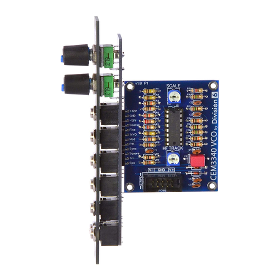
Division 6 NV3340VCOEB Yapım Talimatları
Mikrodenetleyiciler Division 6 NV3340VCOEB için çevrimiçi göz atın veya pdf Yapım Talimatları indirin. Division 6 NV3340VCOEB 3 sayfaları.

What You'll Need:
·CEM3340 VCO Kit
· Soldering Iron
1
Install Diodes
Build the main board first. To make assembly easier, we're going to install
components from shortest to tallest. This way when you flip the board over to
solder them, your work surface will hold them in place.
Let's start with the diodes. To prep the leads, hold the body of the diode and
bend the two leads 90 degrees.
Insert the diodes into the holes marked D1 and D2 on the main PCB. Polarity
does matter for diodes, so when you insert them into the board, make sure
the black stripes on the diodes line up with the stripes on the silkscreen
pattern.
Bend the leads outward underneath the board to hold the diodes in place.
Flip the board over, solder the diode leads, then trim them just above the
solder joint.
For a quick soldering tutorial, visit division-6.com/solder
2
Install Resistors
Working one value at a time, prep the leads of the resistors like you did with
the diodes.
Insert the resistors into their proper locations (see BOM). Polarity doesn't
matter for resistors, but your board will be easier to troubleshoot and look
neater if you line up all the tolerance bands (gold) the same direction. Bend
the leads outward underneath the board to hold the resistors in place.
Flip the board over, solder the resistor leads, then trim them just above the
solder joint.
Make sure you have everything before you start soldering!
· Solder
· Wire Cutters
Continued...
Page 1/3
CEM3340 VCO Build Instructions
· 9mm Socket
· 10mm Socket
3
Install Ceramic Capacitors
Install and solder C1, C2, C3, C4, C6, and C7. Polarity doesn't matter.
4
Install IC Socket
Insert the IC socket into the board. Note that one end of the socket has a
notch in it to indicate which end of the IC has pin 1. Make sure to align the
notch with the notch indicated on the silk screen pattern.
Flip the board over and solder one pin on each corner of the socket. This
makes it easy to reposition the socket in case it isn't seated all the way down
against the board; just reheat the corner pin and adjust the socket position as
necessary.
Once you are happy with the positioning of the socket, solder the remaining
pins. The pins are short enough that they don't need to be trimmed.
Polarity doesn't matter
Polarity DOES matter
Continued...
